Sludge Level Measurement
Sludge Level Measurement
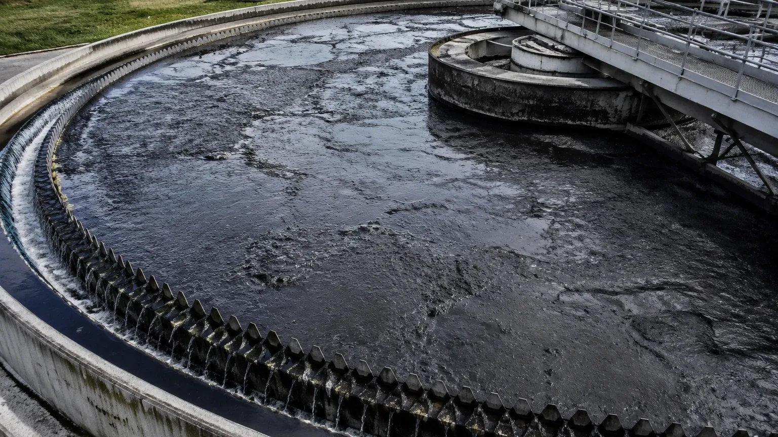
In industrial wastewater treatment, chemical processing, and mining operations, accurate sludge level measurement is a fundamental requirement for process efficiency. Sludge, a semi-solid slurry produced during various industrial and municipal processes, presents unique challenges for instrumentation. Unlike clear liquids, sludge has varying densities, high solids content, and the potential for significant buildup on sensor surfaces. Monitoring the sludge blanket level—the interface between the settled solids and the clarified liquid—allows operators to optimize desludging cycles, manage chemical dosing, and prevent solids carryover into effluent streams.
Effective management of these systems relies on selecting the appropriate measurement technology based on the physical properties of the sludge and the specific dynamics of the tank or clarifier. This guide examines the principles of sludge level measurement, the technologies available, and the practical considerations for successful installation.
Understanding Sludge Level Measurement Principles
Sludge level measurement generally falls into two categories: measuring the top surface of the sludge (in a storage tank) or measuring the interface level between a liquid and a settled sludge layer (in a clarifier or thickener).
The Interface Principle
In many applications, the goal is to locate the "sludge blanket." This requires a sensor capable of distinguishing between two media with different physical properties, such as density or acoustic impedance. For instance, in a secondary clarifier at a wastewater treatment plant, the sensor must penetrate the clarified water to detect the point where the concentration of suspended solids increases significantly.
Time-of-Flight (ToF)
Many modern instruments, including ultrasonic and radar meters, utilize the Time-of-Flight principle. The sensor emits a signal (sound or electromagnetic wave) that travels through the medium, reflects off the sludge surface or interface, and returns to the receiver. By measuring the time taken for this round trip and knowing the speed of the signal in the specific medium, the distance to the sludge can be calculated.
Hydrostatic Pressure
Hydrostatic measurement relies on the principle that the pressure at a specific depth is proportional to the weight of the liquid column above it. While commonly used for liquid level, its application in sludge requires careful consideration of the fluid's changing density. If the solids concentration increases, the pressure will rise even if the physical height remains constant, necessitating sophisticated calibration or dual-sensor compensation.
Key Technologies for Sludge Level Detection
1. Ultrasonic Level Sensors
Ultrasonic sensors are widely used for sludge level measurement due to their cost-effectiveness and reliability in non-contact applications. They emit high-frequency sound pulses. For interface measurement, specialized submerged ultrasonic transducers are often used. These are mounted below the liquid surface and point downward toward the sludge blanket.
* Advantages: No moving parts, relatively low maintenance, and capable of tracking the density gradient of the sludge blanket.
* Limitations: High concentrations of suspended solids in the upper liquid layer can scatter the sound waves, leading to signal loss. Heavy foam on the surface can also absorb the signal.
2. Radar Level Meters
Radar technology uses high-frequency microwave pulses. While non-contact radar is excellent for measuring the top surface of sludge in a storage tank, it is generally not used for submerged interface measurement because microwaves are absorbed by water. However, for thick sludge in open or closed tanks, radar offers high precision.
* Advantages: Unaffected by temperature fluctuations, vacuum, or high pressure. High-frequency radar (e.g., 80 GHz) provides a narrow beam that avoids internal tank obstructions.
* Limitations: Generally limited to surface level rather than submerged interface detection.
3. Hydrostatic Level Transmitters
Hydrostatic transmitters measure the pressure exerted by the sludge column. For sludge applications, flush-diaphragm sensors are preferred to prevent the solids from clogging the pressure port.
* Advantages: Simple installation and highly reliable for heavy, viscous sludge where non-contact methods might fail due to surface turbulence.
* Limitations: Accuracy is dependent on constant density. In sludge thickeners where density varies, errors can occur unless compensated.
4. Optical and Infrared Sensors
Optical sensors measure the attenuation of light or infrared beams. As the solids concentration increases, the light is blocked or scattered. These are often used as "sludge switches" to detect when the blanket reaches a specific height.
* Advantages: Very sensitive to small changes in solids concentration.
* Limitations: Prone to fouling. Even a thin film of biological growth or oil on the lens can cause false readings, necessitating frequent cleaning or automated cleaning systems.
Selection Criteria: Matching Technology to Application
Choosing the right instrument requires an analysis of the process environment. Engineers should evaluate the following factors:
1. Medium Characteristics: Is the sludge primary, secondary, or digested? Primary sludge often contains grit and debris, while secondary sludge is more homogeneous but may have lower density differences compared to the supernatant.
2. Tank Geometry: The presence of scrapers, agitators, and baffles can interfere with sensor signals. Narrow beam angles are essential in cluttered environments.
3. Process Conditions: Temperature, pressure, and the presence of corrosive chemicals (such as those used in pH adjustment) dictate the materials of construction for the sensor (e.g., PVDF, PTFE, or Stainless Steel).
4. Measurement Goal: Is the requirement a continuous level reading for pump control, or a simple point-level alarm to prevent overflow?
For a comprehensive overview of available technologies and detailed product specifications, engineers can refer to the Main Page for technical documentation and application support.
Practical Selection Table for Industrial Sludge
| Technology | Typical Application | Accuracy | Maintenance Level | Key Constraint |
| :— | :— | :— | :— | :— |
| Submerged Ultrasonic | Clarifier Interface | ±10–20 mm | Moderate | Affected by high turbidity in supernatant |
| Non-contact Radar | Sludge Storage Tanks | ±2–5 mm | Low | Cannot measure submerged interface |
| Hydrostatic (Flush) | Digesters / Thick Sludge | ±0.1% of Span | Low | Density must be relatively constant |
| Optical/Infrared | Point Level Detection | N/A (Switch) | High | Requires frequent lens cleaning |
| Guided Wave Radar | Small Tanks / Low Dielectric | ±5 mm | Moderate | Subject to material buildup on probe |
Installation Guidelines and Best Practices
Proper installation is as critical as technology selection. Even the most advanced sensor will fail if placed incorrectly.
Positioning and Clearance
Sensors should be installed away from the tank walls to avoid false reflections (in the case of radar and ultrasonic) and away from the inlet pipes where turbulence and aeration are highest. For clarifiers with rotating scrapers, the sensor must be positioned to avoid physical impact while still capturing a representative area of the sludge blanket.
Avoiding Obstructions
In many sludge tanks, internal structures like ladders, pipes, and heating coils are common. When using ultrasonic or radar meters, ensure the "cone of influence" (the beam angle) is clear of these objects. If an obstruction is unavoidable, many modern transmitters offer "false echo suppression" software to ignore these static signals.
Mounting and Accessibility
Sludge sensors eventually require inspection or cleaning. Mounting sensors on swing-out brackets or using flanged connections that are easily accessible from a walkway is recommended. For hydrostatic sensors, ensuring the cable is properly supported to prevent strain on the diaphragm is essential.
Environmental Protection
Outdoor installations must account for seasonal changes. In cold climates, ice formation on the surface can interfere with non-contact sensors. In tropical environments, condensation inside the sensor housing can lead to electronics failure. Utilizing sensors with high IP ratings (IP68 for submerged, IP66/67 for others) and integrated sunshades or heaters can mitigate these risks.
Addressing Common Challenges and Limitations
Signal Attenuation
In sludge level measurement, signal attenuation is a frequent problem. High-density sludge may absorb ultrasonic energy rather than reflecting it. In these cases, increasing the power of the transducer or switching to a lower frequency can help penetrate the medium. For radar, using a higher frequency (80 GHz) provides better focus and can often overcome light foam.
Material Buildup
Sludge is inherently messy. Over time, fats, oils, and greases (FOG) or biological films can coat the sensor.
* For Ultrasonic/Radar: Buildup on the face of the transducer can cause a "ringing" effect, where the sensor sees the buildup as a level at zero distance.
* Mitigation: Use sensors with self-cleaning faces (vibrating diaphragms) or install automated water-spray cleaning systems that trigger at set intervals.
Density Fluctuations
As noted, hydrostatic sensors are sensitive to density. If a plant processes different types of sludge or if the concentration varies significantly throughout the day, the level reading will drift. In these scenarios, a differential pressure setup or a secondary density-compensating sensor is required to maintain accuracy.
Frequently Asked Questions (FAQ)
Q: Can I use a standard liquid level ultrasonic sensor for sludge interface?
A: Standard ultrasonic sensors are designed for air-to-liquid interfaces. For sludge interface (liquid-to-solid), you need a submerged ultrasonic sensor specifically calibrated for the acoustic properties of water and sludge.
Q: How does foam affect sludge level measurement?
A: Foam is a major obstacle for non-contact sensors. It can absorb ultrasonic waves entirely. Radar is more resistant to foam, but thick, dense foam can still attenuate the signal or cause the radar to measure the top of the foam instead of the sludge surface.
Q: What is the maintenance interval for sludge level sensors?
A: This depends heavily on the sludge type. In biological wastewater treatment, sensors might need cleaning every 2–4 weeks. In cleaner industrial processes, they may run for months without intervention. Automated cleaning systems significantly extend these intervals.
Q: Is radar better than ultrasonic for sludge?
A: For surface measurement in a tank, radar is generally superior due to its higher accuracy and resistance to environmental factors. However, for submerged interface measurement in a clarifier, ultrasonic is the industry standard because radar signals do not penetrate water effectively.
Conclusion
Successful sludge level measurement requires a balance between technology capability and process understanding. By evaluating the specific characteristics of the sludge—such as its tendency to foam, its density stability, and its corrosiveness—operators can select a system that provides reliable data for years. Whether utilizing the precision of radar for storage or the specialized interface detection of submerged ultrasonic sensors, proper installation and a planned maintenance schedule remain the cornerstones of effective solids management. For more detailed engineering support and to view a full range of industrial level instruments, visit the Main Page.