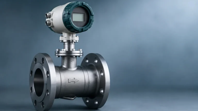
Smart Temperature Transmitter
Smart Temperature Transmitter
In modern industrial automation, the precision of process variables is the foundation of operational safety and efficiency. Among these variables, temperature is perhaps the most frequently measured. A smart temperature transmitter serves as the critical bridge between raw sensing elements—such as Resistance Temperature Detectors (RTDs) or thermocouples—and the control system (PLC/DCS). Unlike traditional analog transmitters, a smart temperature transmitter incorporates a microprocessor that allows for advanced diagnostics, digital communication, and superior linearization of non-linear sensor signals.
For engineers and plant managers, understanding the nuances of these devices is essential for optimizing process loops, especially when temperature data is used to compensate for other measurements like pressure or level. To explore a wider range of industrial measurement solutions, technical professionals often refer to the Main Page of specialized instrumentation providers to compare integrated system capabilities.
Understanding the Measurement Principle
The fundamental role of a smart temperature transmitter is to convert the low-level millivolt (mV) signal from a thermocouple or the ohmic resistance from an RTD into a standardized, interference-resistant signal, typically 4-20 mA DC or a digital protocol like HART, PROFIBUS, or Foundation Fieldbus.
The Signal Processing Chain
1. Input Stage: The transmitter receives the raw signal from the sensor. For an RTD, the transmitter applies a small constant current to measure the voltage drop. For a thermocouple, it measures the mV output and performs Cold Junction Compensation (CJC) to account for the temperature at the transmitter terminals.
2. A/D Conversion: The analog signal is converted into a high-resolution digital value. Smart transmitters typically use 16-bit or 24-bit Sigma-Delta converters to ensure high accuracy.
3. Microprocessor Processing: This is where the "smart" functionality resides. The microprocessor applies linearization algorithms. Since sensors like Type K thermocouples or Pt100 RTDs do not have a perfectly linear relationship between temperature and output, the microprocessor uses mathematical models (such as the Callendar-Van Dusen equation for RTDs) to correct these errors.
4. D/A Conversion and Communication: The processed digital value is converted back to a 4-20 mA analog signal for traditional loops, or it is transmitted directly as a digital value via a communication protocol. The HART protocol allows digital data to be superimposed on the 4-20 mA signal, enabling remote configuration and diagnostics.
Key Components of a Smart Temperature Transmitter
A robust smart temperature transmitter is comprised of several critical sub-systems designed to withstand harsh industrial environments:
* Sensor Input Terminals: Designed to accept various wiring configurations (2-wire, 3-wire, or 4-wire for RTDs).
* Microprocessor Unit (MPU): The brain that handles calculations, calibration data storage, and diagnostic routines.
* Galvanic Isolation: High-quality transmitters provide isolation between the input, output, and power supply (often up to 2.5 kV AC). This protects the control system from ground loops and electrical noise.
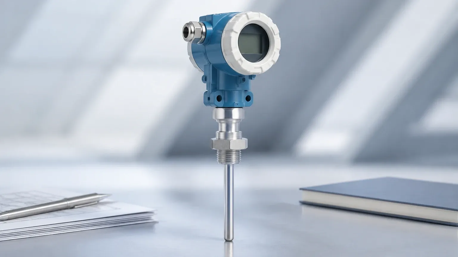
* Housing/Enclosure: Typically made of die-cast aluminum or stainless steel (316L) with IP66/IP67 ratings to protect against moisture and dust.
* Local Display (Optional): An LCD or LED interface that allows technicians to view real-time data and error codes in the field.
Comparison: RTD vs. Thermocouple Input
When selecting a smart temperature transmitter, the choice of the primary sensing element is paramount. The transmitter must be configured to match the specific characteristics of the sensor.
| Parameter | RTD (e.g., Pt100) | Thermocouple (e.g., Type K/J) |
| :— | :— | :— |
| Measurement Range | -200°C to +850°C | -270°C to +2300°C |
| Accuracy | High (Class A/AA) | Medium |
| Stability | Excellent (low drift) | Fair (drifts over time) |
| Response Time | Slower (due to mass) | Fast (small junction) |
| Linearity | Good | Poor (requires heavy processing) |
| Cost | Higher | Lower |
| Vibration Resistance | Fragile | Robust |
Selection Criteria for Industrial Applications
Choosing the right smart temperature transmitter requires a detailed analysis of the process environment and the required control precision. Engineers should consider the following factors:
1. Communication Protocol
While 4-20 mA remains the industry standard, the "smart" aspect is defined by the protocol. HART is the most common, allowing for remote scaling and troubleshooting without interrupting the loop. For fully digital plants, Foundation Fieldbus or PROFIBUS PA provides extensive multi-variable data and device heartbeat monitoring.
2. Form Factor and Mounting
* Head-Mount: The transmitter is installed directly inside the connection head of the sensor. This is compact and reduces the length of low-level signal wires, minimizing noise.
* DIN Rail-Mount: Installed in a control cabinet or junction box. This is ideal for environments where the sensor location is too hot or vibrates too much for electronics.
* Field-Mount: Housed in a dedicated, rugged enclosure (often explosion-proof) for direct installation in the process area.
3. Accuracy and Ambient Temperature Effect
Smart transmitters are rated for accuracy (e.g., ±0.1°C), but this can vary based on the ambient temperature of the transmitter itself. High-tier models feature ambient temperature compensation to ensure the output remains stable whether the transmitter is in a frozen outdoor environment or near a hot furnace.
4. Safety Certifications
In the chemical and oil and gas sectors, transmitters must often carry ATEX, IECEx, or CSA certifications for use in hazardous areas (Intrinsically Safe or Flameproof designs).
The Role of Temperature in Level Measurement Accuracy
In many B2B industrial contexts, temperature measurement is not an isolated requirement. It is a critical auxiliary variable for level measurement. For example, in hydrostatic level sensing, the pressure exerted by a liquid column is dependent on the liquid's density. Since density changes with temperature, a smart temperature transmitter provides the data necessary for the control system to perform real-time density compensation, ensuring the level reading remains accurate.
Similarly, in ultrasonic or radar level applications, temperature variations in the tank's vapor space can affect the speed of sound or the dielectric properties of the medium. Integrating a smart temperature transmitter into the measurement loop allows for a more comprehensive understanding of the vessel's internal dynamics. For those seeking integrated solutions, the Main Page offers insights into how these technologies work in tandem.
Installation and Maintenance Guidelines
Proper installation is as important as the device's specifications. Failure to follow engineering best practices can lead to measurement lag or premature device failure.
Thermowell Considerations
A smart temperature transmitter is rarely in direct contact with the process fluid. Instead, it is inserted into a thermowell.
* Insertion Length: The thermowell should be long enough to ensure the sensing element is in the active flow of the pipe but not so long that it suffers from flow-induced vibration.
* Lagging Extensions: If the pipe is insulated, a lagging extension on the thermowell prevents the transmitter electronics from being exposed to extreme heat or cold conducted through the process connection.
Wiring Best Practices
* Shielding: Use twisted-pair shielded cable to prevent Electromagnetic Interference (EMI).
* Grounding: Ensure the shield is grounded at only one point (usually the control room side) to avoid ground loops.
* 4-Wire RTD: Whenever possible, use 4-wire RTD configurations. This allows the smart transmitter to completely cancel out the lead-wire resistance, which is a major source of error in long-distance runs.
Maintenance and Calibration
Smart transmitters feature "Sensor-Transmitter Matching." By entering the specific calibration constants of an individual sensor into the transmitter's memory, the total loop error can be significantly reduced. Periodic verification should involve checking the transmitter's output against a traceable temperature standard using a dry-block calibrator or a precision oil bath.
Common Challenges and Limitations
Despite their advanced features, smart temperature transmitters have limitations:
* Update Rate: In extremely fast-moving processes, the digital processing time (latency) of a smart transmitter might be slower than a pure analog circuit, though this is rarely an issue in most process industries.
* Power Requirements: Smart electronics require a minimum operating voltage (typically 12-15V DC). On very long cable runs with high resistance, the voltage drop may cause the transmitter to malfunction.
* Complexity: The wealth of diagnostic data can be overwhelming if the control system is not configured to interpret HART status bits effectively.
Frequently Asked Questions (FAQs)
Q: Can a smart temperature transmitter handle multiple sensor inputs?
A: Yes, many dual-input smart transmitters exist. They can monitor two sensors for redundancy (hot backup), differential temperature measurement, or average temperature calculation.
Q: What is the benefit of a "Sensor Drift" alert?
A: Smart transmitters monitor the health of the sensor. If an RTD's resistance begins to change unnaturally (indicating oxidation or moisture ingress), the transmitter can send a diagnostic alarm before the sensor fails completely.
Q: How does a smart transmitter handle a sensor failure?
A: Users can configure a "fail-safe" output. In the event of a broken wire or short circuit, the transmitter can be set to drive the 4-20 mA signal to a high (e.g., 21.0 mA) or low (e.g., 3.6 mA) limit to alert the operator.
Conclusion
The smart temperature transmitter is a cornerstone of precise process control. By providing linearized, accurate, and digitally-enhanced data, these devices enable industries to operate with tighter tolerances and improved safety. Whether used for standalone temperature monitoring or as a compensation tool for complex level measurement tasks, selecting the right transmitter involves a careful balance of sensor compatibility, environmental resilience, and communication requirements. For further technical specifications and product selection guides, visiting the Main Page remains the best step for engineering professionals looking to implement reliable measurement infrastructures.