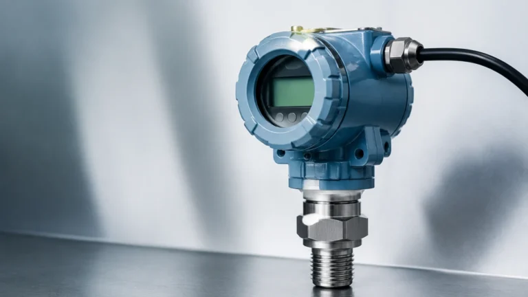
Differential Pressure Level Indicator
Differential Pressure Level Indicator
In the landscape of industrial process control, the differential pressure level indicator remains one of the most versatile and widely implemented technologies for monitoring liquid levels in tanks and vessels. Whether applied in water treatment, chemical processing, or oil and gas production, understanding the nuances of differential pressure (DP) measurement is essential for ensuring operational safety and efficiency. This guide provides a comprehensive technical overview of DP level measurement, covering its underlying principles, hardware configurations, and practical selection criteria.
Principles of Differential Pressure Level Measurement
The fundamental principle behind a differential pressure level indicator is hydrostatic pressure. According to the laws of physics, the pressure exerted by a liquid column at rest is directly proportional to the height of the liquid and its specific gravity (density). The mathematical relationship is expressed as:
P = ρ × g × h
Where:
* P is the hydrostatic pressure.
* ρ (rho) is the density of the liquid.
* g is the acceleration due to gravity (approximately 9.81 m/s²).
* h is the height of the liquid column.
In a practical application, a DP transmitter measures the difference between two pressures. In an open (vented) tank, the "High Pressure" (HP) side of the transmitter is connected to the bottom of the vessel, while the "Low Pressure" (LP) side is vented to the atmosphere. Since the atmospheric pressure acts on both the surface of the liquid and the LP side of the sensor, it cancels out, leaving the hydrostatic pressure as a direct representation of the liquid level.
For closed or pressurized vessels, the LP side of the differential pressure level indicator is connected to the top of the tank (the vapor space). This ensures that any internal vessel pressure is subtracted from the total pressure measured at the bottom, isolating the pressure generated solely by the liquid height.
System Components and Configurations
A complete DP level measurement system involves more than just the transmitter. Depending on the process medium and vessel architecture, several configurations are commonly used:
1. Impulse Piping (Sensing Lines)
Impulse lines are small-diameter pipes that carry the process pressure from the vessel taps to the transmitter. While cost-effective, they require careful maintenance to prevent clogging, freezing, or gas entrapment.
2. Remote Diaphragm Seals
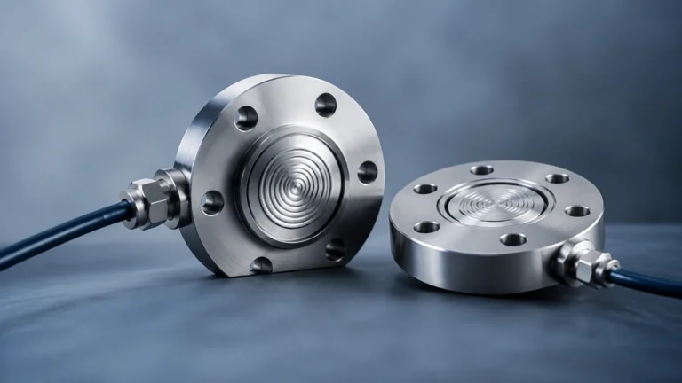
In applications involving corrosive fluids, high temperatures, or hygienic requirements, remote seals are used. These consist of a flexible diaphragm connected to the transmitter via a capillary tube filled with a transmission fluid (such as silicone oil). This setup isolates the instrument from the harsh process environment.
3. Manifolds
A 3-way or 5-way valve manifold is typically installed between the process and the transmitter. This allows for safe isolation, venting, and zero-point calibration without shutting down the entire process.
Installation Considerations: Wet Leg vs. Dry Leg
When measuring level in a closed tank where the vapor may condense into a liquid, engineers must choose between a "dry leg" and a "wet leg" configuration for the LP side.
* Dry Leg: Used when the gas in the vapor space will not condense at ambient temperatures. The LP line remains filled with gas. If condensation occurs, it can collect in the line and create a "head error," leading to false readings.
* Wet Leg: If the vapor is likely to condense (such as steam), the LP line is intentionally filled with a compatible liquid (often the process fluid or water) to a known height. This creates a constant reference pressure. The transmitter is then calibrated to account for this constant liquid head on the LP side, a process known as "suppression."
Selection Criteria for Industrial Applications
Choosing the right differential pressure level indicator requires a detailed analysis of the process conditions. Engineers should evaluate the following factors:
| Criteria | Considerations |
| :— | :— |
| Fluid Density | DP measurement is density-dependent. If the liquid density changes due to temperature fluctuations, the level reading will become inaccurate unless compensated. |
| Vessel Type | Open tanks require single-port or vented measurement; closed tanks require dual-port differential measurement. |
| Pressure Rating | The transmitter must withstand the maximum static pressure of the vessel, not just the differential pressure of the liquid height. |
| Chemical Compatibility | Wetted parts (diaphragms and bolts) must be resistant to the process medium. Common materials include 316L Stainless Steel, Hastelloy, or Tantalum. |
| Temperature Range | High-temperature applications may require remote seals with cooling fins or specialized fill fluids. |
For complex industrial environments requiring high precision, it is often beneficial to Review product options and application support to ensure the selected hardware meets specific regulatory and safety standards.
Practical Selection Table: DP vs. Other Technologies
While DP indicators are a standard choice, comparing them with other technologies like radar or ultrasonic sensors helps in selecting the most reliable solution for a specific site.
| Feature | DP Level Indicator | Radar (Non-Contact) | Ultrasonic |
| :— | :— | :— | :— |
| Primary Principle | Hydrostatic Pressure | Time of Flight (Microwave) | Time of Flight (Sound) |
| Density Sensitivity | High (Requires constant ρ) | None | None |
| Foam/Vapor Impact | Minimal | Low to Moderate | High |
| Installation | Bottom/Side Taps | Top Mounted | Top Mounted |
| Maintenance | Moderate (Impulse lines) | Very Low | Low |
| Cost | Economical | Higher | Moderate |

Limitations and Common Challenges
Despite its reliability, the differential pressure level indicator has specific limitations that must be managed:
1. Density Variations: This is the most significant drawback. If the process fluid's temperature rises, its density typically decreases. Because the DP transmitter measures weight (pressure), it will indicate a lower level even if the physical volume has increased. Modern systems often integrate a temperature sensor to provide real-time density compensation.
2. Clogging and Sediment: In slurries or fluids with high solids content, impulse lines can clog. Using diaphragm seals or "extended diaphragm" transmitters that sit flush with the tank wall can mitigate this risk.
3. Capillary Effects: In remote seal systems, long capillary tubes are sensitive to ambient temperature changes, which can cause the fill fluid to expand or contract, resulting in a zero-shift error.
Installation Best Practices
To ensure the longevity and accuracy of a differential pressure level indicator, follow these engineering guidelines:
* Transmitter Location: Ideally, mount the transmitter below the bottom process tap. This ensures the impulse lines remain full of liquid and helps prevent gas bubbles from being trapped in the sensing lines.
* Slope of Impulse Lines: Impulse lines should be sloped at least 80 mm per meter (1:12 ratio). For liquid service, slope downward toward the transmitter; for gas service, slope upward toward the transmitter.
* Zero Calibration: Always perform a zero-check at the operating pressure. Static pressure effects can cause a small shift in the zero point that is not present at atmospheric pressure.
* Heat Tracing: In cold climates, impulse lines for water or viscous fluids should be heat-traced and insulated to prevent freezing or significant viscosity changes.
Frequently Asked Questions (FAQ)
Q: Can a DP transmitter measure the level of an interface between two liquids?
A: Yes. By measuring the pressure difference between two points in a vessel filled with two immiscible liquids (like oil and water), a DP transmitter can calculate the interface level, provided the densities of both liquids remain relatively constant.
Q: What is "Zero Elevation" and "Zero Suppression"?
A: Zero suppression is used when the transmitter is mounted below the bottom tap, meaning it sees a positive pressure even when the tank is empty. Zero elevation is used in wet-leg applications where the LP side has a constant pressure head that is higher than the HP side when the tank is empty.
Q: How often should a differential pressure level indicator be calibrated?
A: Calibration frequency depends on the criticality of the process and the stability of the instrument. In most industrial applications, an annual verification is standard, though modern digital transmitters with high stability may extend this interval to 2–5 years.
Q: Is DP measurement suitable for vacuum tanks?
A: Yes, but it requires specialized considerations. Remote seals are often preferred in vacuum service to prevent the process fluid from boiling in the impulse lines or to prevent air ingress through fittings.
Conclusion
The differential pressure level indicator remains a cornerstone of industrial instrumentation due to its proven track record and adaptability. By understanding the relationship between pressure and density, and by selecting the appropriate configuration—whether it be a simple dry leg or a complex remote seal system—engineers can achieve highly accurate and repeatable level measurements. When specifying equipment for new projects or retrofits, referring to a comprehensive Main Page for technical specifications and sensor varieties ensures that the chosen solution aligns with both the physical requirements of the vessel and the economic goals of the operation.