Systematic Failures
Systematic Failures
In the field of industrial process control, the reliability of level measurement is paramount to both operational efficiency and plant safety. While hardware components may eventually wear out or break due to random physical degradation, a more insidious category of issues often plagues complex systems: systematic failures. Unlike random failures, which are typically addressed through statistical analysis and Mean Time Between Failure (MTBF) data, systematic failures are inherent to the design, installation, or application of the instrument. They occur deterministically under a specific set of conditions and can only be eliminated by a change in the design, manufacturing process, or operational procedure.
For engineers and procurement specialists, understanding the root causes of systematic failures in level measurement is essential for maintaining Functional Safety (SIL) standards and ensuring long-term uptime. This guide explores the principles of common level measurement technologies, identifies the specific conditions that trigger systematic errors, and provides practical strategies for mitigation.
Measurement Principles and Potential Failure Points
To prevent systematic errors, one must first understand the physics governing the sensors. Different technologies interact with the process medium in unique ways, and each has a specific set of "blind spots" where systematic failures are most likely to occur.
Radar Level Measurement (FMCW and Pulse)
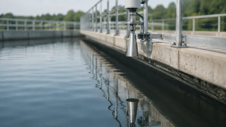
Radar level meters operate on the Time-of-Flight (ToF) principle. Frequency Modulated Continuous Wave (FMCW) radar emits a high-frequency signal that increases in frequency over time. The signal reflects off the liquid surface and returns to the antenna. The difference between the emitted and received frequency is proportional to the distance.
Systematic Risk: Radar is highly reliable but can suffer systematic failures if the dielectric constant ($ε_r$) of the medium is too low (typically < 1.4), leading to signal loss. Furthermore, internal tank obstructions like agitators or heating coils can create "false echoes" that the software may incorrectly identify as the true level if not properly mapped during commissioning.
Ultrasonic Level Sensors
Ultrasonic sensors also use ToF, but they transmit sound waves instead of electromagnetic waves. The sensor measures the time it takes for a mechanical pulse to travel to the surface and back.
Systematic Risk: Because sound requires a medium to travel, changes in the gas composition or temperature in the tank headspace can alter the speed of sound. If the transmitter is not compensated for these variations, a systematic measurement drift occurs. Additionally, heavy foam can absorb the acoustic energy, leading to a "lost echo" failure.
Hydrostatic Level Transmitters
These sensors measure the pressure exerted by a liquid column. The formula used is $P = ρ × g × h$, where $P$ is pressure, $ρ$ is density, $g$ is gravity, and $h$ is the height of the liquid.
Systematic Risk: The most common systematic failure here is density variation. If the process temperature changes significantly, the density of the liquid changes. Since the sensor only measures pressure, it will report an incorrect level unless a secondary temperature sensor is used to calculate the density correction in real-time.
Defining Systematic Failures in the B2B Context
In the context of IEC 61508 and IEC 61511 standards, a systematic failure is defined as a failure related in a deterministic way to a certain cause, which can only be eliminated by a modification of the design or the manufacturing process, operational procedures, documentation, or other relevant factors.
In industrial level measurement, these often manifest as:
1. Software Bugs: Logic errors in the signal processing algorithms that cause the device to lock up or report a static value under specific turbulence conditions.
2. Environmental Mismatch: Using an ultrasonic sensor in a vacuum or a high-pressure environment where the physics of sound propagation are compromised.
3. Installation Errors: Mounting a radar sensor too close to a tank wall, causing the beam to interact with the wall (skin effect) and providing a consistently offset reading.
4. Specification Gaps: Failing to account for chemical compatibility, leading to the gradual corrosion of a diaphragm which eventually causes a predictable, non-random failure.
When evaluating high-reliability instrumentation, engineers often visit the Main Page of leading manufacturers to compare technical specifications and ensure the selected technology aligns with the physical realities of their application.
Systematic Risks by Technology Type
Understanding where each technology is prone to systematic issues allows for better risk assessment during the FEED (Front-End Engineering Design) phase.
1. Radar (Non-Contact and Guided Wave)
* Vapor and Condensation: While radar is generally unaffected by vapors, extremely heavy steam can attenuate very high-frequency signals (e.g., 80 GHz). If condensation forms a bridge across the antenna, the sensor may report a "high level" regardless of the actual liquid position.
* Refractive Index Changes: In high-pressure steam applications (like boiler drums), the dielectric constant of the steam space changes, slowing down the radar signal and causing a systematic under-reporting of the level.
2. Ultrasonic Sensors
* Wind and Turbulence: In outdoor sumps, high wind speeds can "blow" the acoustic pulse away from the receiver.
* Acoustic Noise: Heavy machinery or pneumatic filling nearby can create ultrasonic noise that interferes with the sensor's ability to distinguish its own pulse.
3. Magnetic Level Gauges
* Float Buoyancy: If the liquid density drops below the design specification of the float, the float will sink. This is a deterministic, systematic failure caused by incorrect specification.
* Magnetic Particles: If the process fluid contains ferrous particles, they can accumulate on the internal magnet, eventually weighing it down or causing it to stick.
Selection Table: Technology vs. Systematic Failure Drivers
| Failure Driver | Radar (80GHz) | Ultrasonic | Hydrostatic | Magnetic Gauge |
| :— | :— | :— | :— | :— |
| Density Changes | No Impact | No Impact | High Risk | Moderate Risk |
| Vacuum Conditions | No Impact | Total Failure | No Impact | No Impact |
| Heavy Foam | Moderate Risk | High Risk | No Impact | No Impact |
| Internal Obstructions | Moderate Risk | Moderate Risk | No Impact | No Impact |
| Temperature Swings | No Impact | High Risk | Moderate Risk | No Impact |
| Build-up/Coating | Low Risk | Moderate Risk | High Risk | Moderate Risk |

Installation Considerations to Prevent Systematic Errors
Even the best instrument will fail systematically if installed incorrectly. To ensure accuracy, follow these engineering guidelines:
* The 1/10 Rule for Radar: Ensure the radar beam is kept away from the tank wall by at least 1/10th of the total tank height to avoid interference.
* Stilling Wells: In tanks with heavy agitation or foam, using a stilling well or a bypass chamber can eliminate the systematic noise and surface turbulence that confuses non-contact sensors.
* Temperature Compensation: For hydrostatic and ultrasonic sensors, always ensure the system includes a temperature element. For hydrostatic sensors, this is often integrated into the transmitter body; for ultrasonic, it should be near the transducer face.
* Nozzle Geometry: Ensure that the mounting nozzle does not protrude into the tank in a way that creates a dead zone or a reflection point for the signal. The nozzle should be as short as possible, particularly for ultrasonic and radar devices.
Mitigation and Redundancy Strategies
To minimize the impact of systematic failures, particularly in safety-critical applications, engineers employ "Diversity."
Functional Diversity
Instead of using two identical radar meters (which might both fail systematically if the process fluid foams), a plant might use one Radar Level Meter and one Hydrostatic Transmitter. Because these technologies rely on different physical principles (Time-of-Flight vs. Pressure), they are unlikely to be affected by the same systematic cause. If the density changes, the hydrostatic sensor might drift, but the radar will remain accurate. If foam occurs, the radar might struggle, but the hydrostatic sensor will remain stable.
Software and Logic Testing
Modern level meters allow for "Echo Mapping." This is a process where the tank is scanned while empty, and all static reflections (from ladders, pipes, etc.) are recorded and ignored by the software. This is a crucial step in preventing systematic false-positive level readings.
Frequently Asked Questions (FAQs)
Q: Can systematic failures be calculated using MTBF?
A: No. MTBF (Mean Time Between Failure) only measures random hardware failures. Systematic failures are 100% predictable if the triggering condition is met. They are managed through rigorous design and application reviews rather than statistical probability.
Q: How does SIL (Safety Integrity Level) address systematic failures?
A: SIL certification involves "Systematic Capability" (SC). A device rated SC3, for example, has been developed using rigorous processes to minimize the likelihood of design or software errors, making it suitable for use in SIL 3 safety functions.
Q: Why is density a problem for hydrostatic sensors but not for radar?
A: Hydrostatic sensors measure weight (force), which depends on mass and density. Radar measures distance using electromagnetic waves, which are independent of the mass or density of the liquid, provided the liquid reflects the signal.
Q: Can a systematic failure be fixed with maintenance?
A: Generally, no. While cleaning a coated sensor is maintenance, a systematic failure usually requires a change in the system—such as moving the sensor to a better location, changing the technology, or updating the software parameters to better handle the process conditions.
Conclusion
Systematic failures represent a significant challenge in industrial level measurement because they cannot be predicted by traditional reliability math. They require a deep understanding of the interaction between the instrument's measurement principle and the process environment. By selecting the appropriate technology, adhering to strict installation guidelines, and employing diverse redundancy, operators can significantly reduce the risk of these deterministic errors. For those seeking reliable hardware designed to withstand demanding industrial conditions, reviewing the Main Page of specialized manufacturers is the first step toward a robust measurement strategy.