Tank Water Sensor
Tank Water Sensor
In industrial and municipal water management, the selection of an appropriate tank water sensor is a critical engineering decision that impacts operational efficiency, safety, and cost-effectiveness. Whether managing a simple storage cistern, a complex wastewater treatment basin, or a high-pressure boiler feed tank, the technology used to monitor liquid levels must align with the specific physical and chemical environment of the application. This guide provides a technical overview of the primary measurement principles, selection criteria, and installation requirements for modern water level sensing technologies.
Understanding Tank Water Sensor Technologies
A tank water sensor is not a single device but a category of instruments designed to convert the physical level of water into a readable signal, such as a 4-20mA analog output, a digital Modbus signal, or a simple switch contact. These sensors are categorized based on their measurement method: non-contact (radar and ultrasonic) or contact (hydrostatic, magnetic, and float-based).
Choosing the correct technology requires an understanding of how environmental factors—such as vapor, foam, turbulence, and tank geometry—interact with the sensing signal. For comprehensive product specifications and technical support across these categories, engineers often consult the Main Page of specialized manufacturers to compare performance metrics.
Measurement Principles and Physics
Before selecting a sensor, it is essential to understand the physics governing each measurement type. Each principle has inherent strengths and limitations based on the medium's properties and the tank's atmospheric conditions.
1. Ultrasonic (Time-of-Flight)
Ultrasonic sensors emit high-frequency sound waves from a transducer located at the top of the tank. These waves travel through the air, reflect off the water surface, and return to the sensor. The device calculates the distance based on the time it takes for the echo to return.
* Principle: $Distance = (Speed of Sound \times Time) / 2$.
* Considerations: The speed of sound is affected by air temperature. Most industrial ultrasonic sensors include integrated temperature compensation to maintain accuracy.
2. Radar (Electromagnetic Waves)
Radar sensors operate similarly to ultrasonic sensors but use high-frequency electromagnetic waves (typically in the 26GHz or 80GHz range) instead of sound. Because light speed is constant and does not require a medium, radar is unaffected by temperature fluctuations, vacuum, or high pressure.
* Principle: Time-of-Flight or Frequency Modulated Continuous Wave (FMCW).
* Strength: Radar can penetrate steam and dust, making it superior for hot water tanks or outdoor reservoirs where fog may occur.
3. Hydrostatic Pressure
Hydrostatic sensors measure the weight of the liquid column above a sensing diaphragm. Since water has a known density, the pressure at the bottom of the tank is directly proportional to the height of the water.
* Principle: $P = \rho \cdot g \cdot h$ (where $P$ is pressure, $\rho$ is density, $g$ is gravity, and $h$ is height).
* Application: These are often submersible sensors dropped to the bottom of a well or tank, or externally mounted at the base of the vessel.
4. Magnetic Level Gauges and Switches
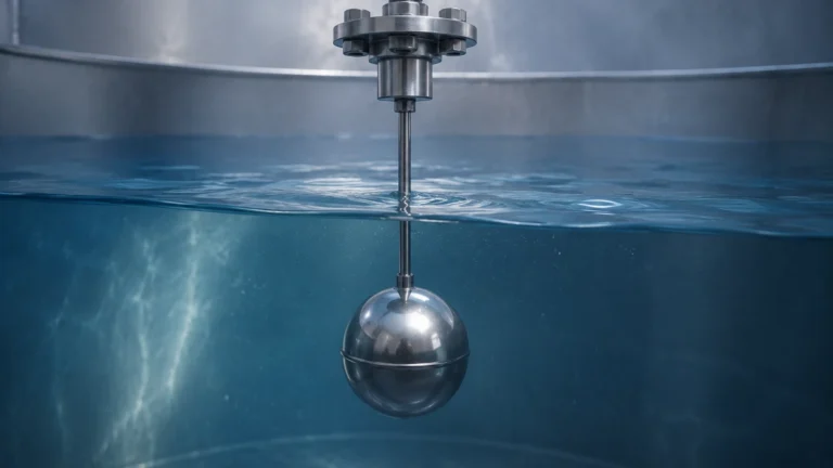
Magnetic sensors utilize a float containing a permanent magnet. As the water level changes, the float moves along a stem or outside a chamber, actuating reed switches or moving a magnetic indicator. This is a purely mechanical-to-electrical or mechanical-to-visual interface.
Selection Criteria for Industrial Water Tanks
Selecting a tank water sensor involves more than just measuring height. Engineers must evaluate the following parameters to ensure long-term reliability:
1. Water Characteristics: Is the water potable, deionized, or wastewater containing solids? Deionized water may require non-contact sensors to prevent contamination, while wastewater may require non-clogging hydrostatic diaphragms.
2. Tank Geometry: Tall, narrow tanks may cause signal interference for ultrasonic sensors due to wall reflections. In such cases, narrow-beam 80GHz radar or hydrostatic transmitters are preferred.
3. Process Conditions: High-temperature water (above 80°C) creates steam, which can attenuate ultrasonic signals. Radar or hydrostatic sensors are better suited for these environments.
4. Accuracy Requirements: For inventory control or billing, high-precision radar (accuracy within ±2mm) is necessary. For simple pump control (on/off), a basic float switch or ultrasonic sensor is usually sufficient.
Comparative Selection Table
The following table summarizes the performance characteristics of the most common tank water sensor technologies used in industrial applications.
| Technology | Typical Accuracy | Measurement Range | Contact Type | Key Advantage | Major Limitation |
| :— | :— | :— | :— | :— | :— |
| Ultrasonic | ±0.25% of range | 0.3m – 15m | Non-contact | Low cost, easy install | Affected by foam and steam |
| Radar (80GHz) | ±2mm | 0.1m – 30m+ | Non-contact | Unaffected by vapors | Higher initial investment |
| Hydrostatic | ±0.1% to 0.5% | 1m – 200m | Contact | Simple, works in deep wells | Sensitive to density changes |
| Magnetic Float | ±5mm to 10mm | 0.5m – 6m | Contact | Visual + Electrical | Moving parts can scale/clog |
| Capacitance | ±1% | 0.1m – 3m | Contact | Good for small tanks | Requires calibration per media |
Installation Best Practices and Considerations
Correct installation is as important as sensor selection. Even the most advanced tank water sensor will fail to provide accurate data if positioned incorrectly.
Mounting Position
* Avoid the Center: In cylindrical tanks, avoid mounting non-contact sensors (ultrasonic/radar) exactly in the center, as this can amplify unwanted echoes from the tank walls.
* Inflow Interference: Never install a sensor directly above the water inlet. The turbulence and splashing from incoming water will create "noise" and lead to erratic readings.
* Obstructions: Ensure the sensor’s signal path is clear of internal ladders, heating coils, or agitators. Radar sensors with narrow beam angles are better at "avoiding" these obstructions.
Dead Zones (Blocking Distance)
Every non-contact tank water sensor has a "dead zone" or "blocking distance" directly beneath the transducer (typically 10cm to 50cm). If the water level rises into this zone, the sensor cannot provide a reading. To mitigate this, sensors should be mounted on a nozzle or standpipe to raise the transducer above the maximum possible fill level.
Venting and Pressure
For hydrostatic sensors in sealed tanks, a vented cable or a differential pressure transmitter is required to compensate for changes in atmospheric pressure or tank head pressure. Failure to vent the sensor will result in significant errors as the weather or internal tank pressure changes.
Limitations and Common Risks
Engineers should be aware of the following risks when deploying water level instrumentation:
* Foam Accumulation: Heavy foam on the water surface acts as an insulator for ultrasonic and radar waves. While radar handles light foam better, thick, dense foam may require a hydrostatic sensor or a guided wave radar (GWR).
* Scaling and Buildup: In hard water applications, calcium carbonate can build up on contact-based sensors (like floats or capacitance probes), causing them to stick or drift. Non-contact sensors are the standard solution for high-scaling environments.
* Chemical Compatibility: When measuring water treated with chlorine, acids, or bases, ensure the wetted materials (e.g., PVDF, PTFE, or 316L Stainless Steel) are chemically resistant to the additives.
* Lightning and Surges: Since many water tanks are located outdoors or at high elevations, sensors are vulnerable to lightning strikes. Utilizing sensors with integrated surge protection and proper grounding is essential for outdoor installations.
Frequently Asked Questions (FAQs)
Q: Can one sensor be used for both water and oil in the same tank?
A: If using a hydrostatic sensor, no, because the density of oil and water differs. However, a radar sensor measures the top surface regardless of the liquid type. To measure the interface (where water and oil meet), a Guided Wave Radar (GWR) or a specialized interface float is required.
Q: How often does a tank water sensor need calibration?
A: Hydrostatic and ultrasonic sensors should typically be checked annually. Radar sensors are highly stable and may only require verification every 2-3 years, depending on the criticality of the process.
Q: Is wireless transmission available for remote tanks?
A: Yes, many modern sensors support LoRaWAN, NB-IoT, or cellular protocols, allowing for remote monitoring of water levels in locations where running signal cables is cost-prohibitive.
Q: What is the best sensor for a tank with an agitator?
A: Radar is often the best choice due to its ability to filter out "false echoes" from moving blades using software algorithms. Alternatively, a hydrostatic sensor is unaffected by surface turbulence caused by the agitator.
Conclusion
Identifying the right tank water sensor requires a balanced evaluation of the physical environment, required precision, and budget. While ultrasonic sensors remain a popular choice for general-purpose water monitoring, the increasing affordability of 80GHz radar has made it the preferred solution for challenging industrial environments involving steam or narrow geometries. For deep-well or high-pressure applications, hydrostatic transmitters remain the industry standard. By adhering to proper installation guidelines and understanding the limitations of each measurement principle, facility managers can ensure reliable water level data for years to come.