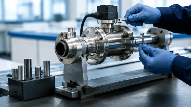
Thermal Flow Switch
Thermal Flow Switch
In the landscape of industrial process control, the ability to reliably detect the presence or absence of flow is fundamental to protecting equipment and ensuring operational efficiency. The thermal flow switch, often referred to as a calorimetric or thermal dispersion flow switch, has emerged as a preferred solution for many engineers due to its lack of moving parts and high sensitivity. Unlike mechanical paddle or piston switches that are prone to wear and clogging, thermal flow switches utilize the physical properties of heat transfer to monitor fluid movement. This article provides a technical overview of their operating principles, selection criteria, installation requirements, and practical limitations within industrial environments.
Understanding the Thermal Dispersion Principle
The operation of a thermal flow switch is based on the principle of thermal dispersion, or the calorimetric effect. The sensing probe typically contains two temperature sensors (usually Platinum RTDs—Resistance Temperature Detectors) located within the tip that is immersed in the fluid stream.
One sensor is the "reference sensor," which measures the actual temperature of the process medium. The second sensor is the "active sensor," which is heated to a constant temperature difference above the reference sensor. When the fluid is stationary (no-flow condition), the heat dissipated from the active sensor is minimal, and the temperature difference between the two sensors remains at its maximum.
As the fluid begins to flow, it carries heat away from the active sensor—a process known as convective cooling. The rate of heat loss is directly proportional to the flow velocity of the medium. The electronics within the switch monitor the power required to maintain the temperature differential or measure the narrowing of the temperature gap. Once the flow rate reaches a pre-defined threshold (the set point), the switch changes its output state (e.g., from N.O. to N.C. or vice versa).
Because this method relies on the thermal conductivity and heat capacity of the fluid, the thermal flow switch is highly effective for both liquids and gases, provided the electronics are calibrated for the specific medium. For a comprehensive look at how these sensors integrate into broader automation systems, engineers can Review product options and application support to find compatible hardware for specific process architectures.
Key Components and Construction
To withstand the rigors of industrial applications, thermal flow switches are constructed with high-grade materials and robust electronics. The primary components include:
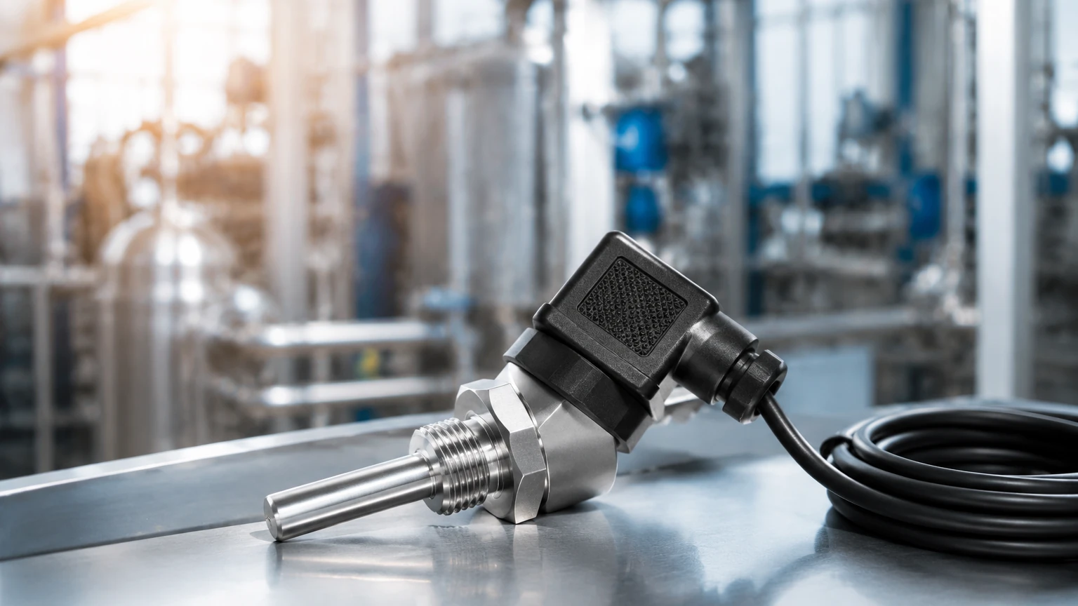
1. The Sensing Probe: Usually manufactured from Stainless Steel (304 or 316L), but often available in exotic alloys like Hastelloy or Monel for highly corrosive chemical environments. The probe must be fully sealed to protect the RTDs from the process media.
2. The Housing: This contains the signal processing electronics. Industrial versions often feature IP65 or IP67 ratings, and for hazardous areas, explosion-proof (Ex d) or intrinsically safe (Ex i) housings are standard.
3. The Interface: Most switches include an LED array to provide local visual feedback. This typically shows the current flow status relative to the set point, allowing technicians to see at a glance if the system is operating within parameters.
4. Adjustment Potentiometer/Buttons: These allow the user to set the switching point. In modern digital versions, this may be handled via a menu-driven display or a communication protocol like IO-Link.
Selection Criteria for Industrial Applications
Selecting the correct thermal flow switch requires a detailed understanding of the process conditions. Because these devices are sensitive to the thermal properties of the fluid, a "one size fits all" approach is rarely successful. Engineers should evaluate the following parameters:
Media Type and Properties
The thermal conductivity of the fluid is the most critical factor. Water has high thermal conductivity and is an ideal medium for these switches. Oils and hydrocarbons have lower conductivity, requiring more sensitive electronics or higher heating power. If the media changes frequently, the switch may require recalibration.
Operating Temperature and Pressure
Standard industrial thermal flow switches can typically handle temperatures from -20°C to +80°C, though high-temperature versions can reach up to 150°C or higher. Pressure ratings are equally important; while many probes can withstand 100 bar (1450 psi), high-pressure applications require specialized heavy-duty probe designs.
Pipe Size and Flow Velocity
Thermal switches are velocity-based devices. In very large pipes, the probe must be long enough to reach the active flow zone (usually at least 15% of the pipe diameter). Conversely, in very small pipes (below 15 mm), the physical presence of the probe might cause a significant pressure drop or localized turbulence.
Practical Selection Table
| Application | Recommended Material | Flow Range (Liquid) | Flow Range (Gas) | Typical Industry |
| :— | :— | :— | :— | :— |
| Cooling Water Loops | SS316L | 1 to 150 cm/s | N/A | Power Generation |
| Lubrication Systems | SS316L | 3 to 300 cm/s | N/A | Heavy Machinery |
| Air Duct Monitoring | Aluminum / SS304 | N/A | 2 to 20 m/s | HVAC / Ventilation |
| Chemical Dosing | Hastelloy C | 1 to 100 cm/s | N/A | Chemical Processing |
| Pump Run-Dry Protection | SS316L | 1 to 50 cm/s | N/A | Water Treatment |
Installation Considerations and Best Practices
Proper installation is the most significant factor in ensuring the long-term reliability of a thermal flow switch. Since the device measures heat dissipation at a specific point, the flow profile at that point must be stable and representative of the total flow.
1. Straight Pipe Runs
To avoid turbulence, which can cause erratic switching, the switch should be installed in a straight section of pipe. A general rule of thumb is to allow for at least 5 times the pipe diameter (5D) of straight pipe upstream of the sensor and 3 times the pipe diameter (3D) downstream. If a pump or valve is located immediately upstream, the required straight run may increase to 10D or 20D.
2. Orientation
In liquid applications, the pipe must always be full. For horizontal pipes, the sensor should ideally be installed from the side. Installing from the top can lead to errors if air pockets develop, while installing from the bottom can cause the sensor to be covered by sediment or sludge, which acts as an insulator and prevents accurate measurement.
3. Immersion Depth
The tip of the probe, where the RTDs are located, must be fully immersed in the moving fluid. In larger pipes, ensure the probe extends past the boundary layer near the pipe wall, where flow velocity is significantly lower due to friction.
4. Wiring and Interference
Thermal flow switches are electronic instruments. Ensure that signal cables are shielded and kept away from high-voltage power lines or variable frequency drives (VFDs) that could induce electrical noise and cause false triggering.
Limitations and Operational Constraints
While highly versatile, the thermal flow switch is not suitable for every application. Understanding its limitations prevents premature failure or inaccurate readings.
* Response Time: Because the technology relies on thermal mass and heat transfer, there is an inherent delay. While some units respond in 1 to 2 seconds, others may take up to 10 seconds to register a change in flow. This makes them unsuitable for applications requiring instantaneous shut-off (e.g., fast-acting water hammer protection).
* Scaling and Coating: If the process medium is prone to leaving deposits (like calcium buildup in hard water or paraffin in oil), a layer of insulation will form on the probe. This reduces the heat transfer efficiency, leading the switch to "think" the flow is slower than it actually is. Regular cleaning is required in these environments.
* Fluid Temperature Fluctuations: Rapid changes in the temperature of the process medium can momentarily confuse the switch. While most modern units feature temperature compensation, a sudden 20°C jump in fluid temperature may cause a brief false alarm as the reference and active sensors re-stabilize.
* Viscosity Sensitivity: High-viscosity fluids (like heavy resins) do not transfer heat as efficiently as water. The switch must be specifically calibrated for high-viscosity media to ensure the set points remain accurate.
Frequently Asked Questions (FAQ)
Q: Can a thermal flow switch be used for both liquids and gases?
A: Yes, but the calibration is different. Gases have much lower thermal conductivity and heat capacity than liquids. Most manufacturers provide specific models or selectable modes for liquid versus gas applications.
Q: How do I know if the sensor is fouled?
A: If the switch indicates a "no-flow" condition even when the pump is running and the pipe is full, or if the LED display shows a consistently low flow velocity regardless of actual pump speed, the probe likely has a coating of scale or debris.
Q: Is there a maximum flow velocity?
A: While there is no theoretical maximum for the thermal principle, extremely high velocities in liquid (above 5 m/s) can cause mechanical stress on the probe or cavitation. For gases, the limit is usually around 50-100 m/s depending on the design.
Q: Does the switch require periodic calibration?
A: In stable, clean environments, these switches are virtually maintenance-free. However, in critical safety applications or where media properties drift, an annual functional check is recommended.
Conclusion
The thermal flow switch provides a robust, low-maintenance alternative to mechanical flow monitoring devices. By leveraging the calorimetric principle, it offers high sensitivity and reliability across a wide range of industrial sectors, from protecting expensive pumps in water treatment plants to monitoring cooling air in electronic cabinets. When selecting a switch, engineers must prioritize material compatibility and understand the thermal characteristics of their specific media. For those seeking detailed technical specifications or customized measurement solutions, the Main Page of industrial instrumentation providers offers a wealth of data on integrating these sensors into modern process control loops.