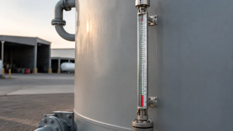
Thermowel
Thermowel
In the complex landscape of industrial process control, the term "thermowel"—frequently used interchangeably with the standardized term thermowell—refers to one of the most critical yet often overlooked components in a measurement loop. Whether managing a chemical reactor, a water treatment facility, or a high-pressure steam line, protecting the primary sensing element is paramount to ensuring long-term accuracy and safety.
For engineers and procurement specialists, understanding the nuances of thermowel design, material selection, and installation is essential. This guide provides a technical overview of how these protective conduits function, their relationship with level measurement systems, and the criteria required to select the right solution for demanding industrial environments.
Principles of Operation and Protective Function
A thermowel is essentially a pressure-tight cylindrical fitting used to isolate a temperature sensor, such as an RTD (Resistance Temperature Detector) or a thermocouple, from the process media. In industrial automation, the sensor itself is often fragile and susceptible to damage from high pressures, corrosive chemicals, or high-velocity flows.
The Heat Transfer Mechanism
The primary measurement principle involves conduction. The thermowel is inserted into the process vessel or pipe, where it reaches thermal equilibrium with the fluid. The internal sensor then measures the temperature of the thermowel's inner wall. To ensure accuracy, the air gap between the sensor and the internal wall of the thermowel must be minimized, often through the use of spring-loaded sensors or heat-conductive pastes.
Mechanical Isolation
Beyond temperature transfer, the thermowel serves as a mechanical barrier. It allows the sensor to be removed or replaced without breaking the process seal or shutting down the system. This is a vital feature for continuous processes where downtime is costly. By maintaining the integrity of the pressure vessel, the thermowel ensures that even if a sensor fails, the process fluid remains contained.
Key Evaluation Criteria for Thermowel Selection
Selecting a thermowel requires more than just matching a thread size. Engineers must evaluate the process conditions against several mechanical and chemical factors. The following table outlines common materials and their typical applications in industrial settings.
Material Selection Table
| Material | Metric Equivalent | Common Applications | Pros/Cons |
| :— | :— | :— | :— |
| 316 Stainless Steel | 1.4401 | Water treatment, food and beverage, general chemicals. | Excellent corrosion resistance; cost-effective for standard use. |
| Hastelloy C-276 | 2.4819 | Highly corrosive acids, chlorine, and sour gas. | Superior chemical resistance; significantly higher cost. |
| Monel 400 | 2.4360 | Sea water, hydrofluoric acid, and salt solutions. | High strength; resistant to stress-corrosion cracking. |
| Inconel 600 | 2.4816 | High-temperature furnaces, heat treating. | Maintains strength at temperatures exceeding 1000°C (1832°F). |
Shank Design
The geometry of the thermowel (the "shank") impacts its performance under flow conditions:
1. Straight: Uniform diameter along the entire immersion length. Best for low-velocity flows.
2. Stepped: Features a reduced diameter at the tip to improve response time while maintaining rigidity at the base.
3. Tapered: Provides a high strength-to-weight ratio, making it ideal for high-velocity applications where vibration is a concern.
Integration with Level Measurement Systems
While a thermowel is a temperature-related component, its role in level measurement is significant, particularly in hydrostatic and ultrasonic applications. In many industrial tanks, the density of a liquid changes with its temperature. Since hydrostatic level transmitters measure the pressure exerted by a liquid column, an accurate temperature reading is required to calculate the true level.
In these integrated systems, a thermowel-protected temperature sensor provides the data necessary for the PLC (Programmable Logic Controller) to perform density compensation. For professionals seeking comprehensive instrumentation packages, exploring the Main Page of a specialized manufacturer like Welk can provide insights into how temperature and level sensors are paired for high-accuracy industrial automation.
For example, in a deep-well water application, a hydrostatic level sensor may be submerged at 50 meters (approx. 164 feet). If the water temperature fluctuates, the density shift could result in a level error of several centimeters. A nearby thermowel housing an RTD ensures the system adjusts for these variations in real-time.
Installation Best Practices
Proper installation is the difference between a reliable measurement and a catastrophic mechanical failure. The following guidelines should be strictly followed:
Immersion Length
The immersion length (often referred to as the "U" length) must be sufficient to ensure the sensing element is fully submerged in the process stream. A general rule of thumb for pipes is that the tip should reach between one-third and two-thirds of the pipe diameter. For tanks, a minimum immersion of 50 mm (approx. 2 inches) into the liquid is typically required to avoid "stem conduction" errors, where the ambient temperature outside the tank influences the reading.
Orientation
In piping systems, the thermowel should ideally be installed at an elbow or at a 45-degree angle pointing against the flow. This orientation increases the surface area exposed to the fluid and reduces the impact of stagnant pockets of liquid, leading to a more representative temperature reading.
Connection Types
* Threaded: Common for low-pressure applications; easy to install but prone to leaks if not properly sealed with PTFE tape or sealant.
* Flanged: The standard for high-pressure and high-temperature industrial processes. They offer a robust seal and are easier to clean in hygienic applications.
* Socket-Weld: Used in permanent installations where leakage cannot be tolerated, such as in steam lines.

Limitations and Common Risks
Despite their robust nature, thermowells are subject to physical laws that can lead to failure if not properly engineered.
Wake Frequency and Vibration
When fluid flows past a cylindrical thermowel, it creates a wake (Von Karman vortices). If the frequency of these vortices matches the natural frequency of the thermowel, resonance occurs. This can lead to rapid metal fatigue and eventual snapping of the thermowel. Engineers should perform a wake frequency calculation (per ASME PTC 19.3 TW) for any application involving high-velocity fluids.
Response Time Lag
Because the heat must pass through the metal wall of the thermowel and then through the air gap to the sensor, there is an inherent delay in temperature measurement. In fast-acting control loops, this lag can cause instability. Using a stepped shank or a thermowel with a higher thermal conductivity material can mitigate this issue.
Corrosion and Erosion
In abrasive slurries or highly acidic environments, the wall of the thermowel will thin over time. Regular inspection intervals are necessary. If the wall thickness decreases beyond a certain point, the internal pressure of the process could cause the thermowel to burst, ejecting the sensor and creating a hazardous leak.
Summary of Selection Steps
Before finalizing a project specification for a thermowel, the following steps should be confirmed:
1. Process Media: Is the material compatible with the chemical composition of the fluid?
2. Pressure/Temperature Rating: Does the flange or thread rating exceed the maximum possible process pressure (including surges)?
3. Velocity Profile: Has a wake frequency calculation been performed for the maximum expected flow rate?
4. Immersion Depth: Is the sensor positioned deep enough to avoid ambient temperature interference?
5. Maintenance Access: Is there enough clearance to remove the sensor from the thermowel for calibration?
Frequently Asked Questions (FAQs)
Q: Can I use a thermowel in a vacuum system?
A: Yes, but the connection (typically flanged or welded) must be rated for vacuum service to prevent air ingress into the process.
Q: How often should a thermowel be inspected?
A: In non-corrosive environments, an annual visual inspection during plant shutdowns is standard. In corrosive or high-velocity applications, ultrasonic thickness testing should be performed every 6 to 12 months.
Q: What is the difference between a thermowel and a protection tube?
A: A thermowel is typically machined from solid bar stock and is designed for high-pressure applications. A protection tube is often made from welded pipe or ceramic and is used for low-pressure, high-temperature applications like furnace exhausts.
Q: Does the thermowel affect the accuracy of my level meter?
A: Indirectly, yes. If your level meter relies on density (like hydrostatic sensors), an inaccurate temperature reading caused by a poorly designed thermowel will lead to an incorrect level calculation.
For more information on selecting the appropriate instrumentation for your specific industrial application, you can Review product options and application support to ensure your system meets the necessary safety and precision standards. By integrating high-quality protective components like the thermowel with advanced level measurement technology, facilities can achieve higher operational efficiency and reduced maintenance costs.