Tm101
Tm101
In the field of industrial automation and process control, accurate level measurement is a fundamental requirement for operational safety, inventory management, and efficiency. The TM101 series represents a specialized category of level transmitters designed to meet the rigorous demands of modern industrial environments. Whether utilized in water treatment facilities, chemical processing plants, or oil and gas storage, understanding the technical nuances of the TM101 is essential for engineers and procurement specialists looking to optimize their instrumentation suites.
This guide provides a comprehensive technical overview of the TM101, detailing its measurement principles, selection criteria, installation requirements, and maintenance protocols. By aligning these technical capabilities with specific application needs, facilities can ensure long-term reliability and minimize the total cost of ownership.
Core Measurement Principles of the TM101 Series
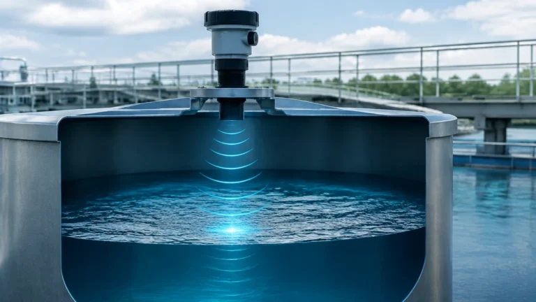
The TM101 primarily operates on the principle of ultrasonic time-of-flight (ToF) measurement. This non-contact method is highly valued in industrial applications because it eliminates the risk of sensor corrosion or mechanical wear associated with contact-based probes.
The Ultrasonic Pulse-Echo Method
The device functions by emitting a series of high-frequency ultrasonic pulses from its transducer face. These sound waves travel through the air or gas space above the medium and are reflected back to the sensor upon hitting the surface of the liquid or solid. The TM101’s internal microprocessor measures the exact time interval between the emission of the pulse and the reception of the echo.
Using the known speed of sound in the specific medium (usually air), the distance is calculated using the formula:
Distance = (Speed of Sound × Time) / 2
Once the distance to the material surface is determined, the transmitter subtracts this value from the total tank height (configured during setup) to provide an accurate level reading. This data is then converted into a standard industrial output, such as a 4-20mA signal or a digital communication protocol like HART or RS485.
Signal Processing and Echo Filtering
One of the defining characteristics of the TM101 series is its advanced signal processing capability. In industrial tanks, internal obstructions such as agitators, ladders, or heating coils can create false echoes. The TM101 utilizes sophisticated algorithms to filter out these "noise" signals, focusing only on the true reflection from the material surface. This ensures stability even in complex vessel geometries.
Technical Specifications and Selection Criteria
Selecting the correct TM101 configuration requires a detailed analysis of the process environment. The following table outlines the standard technical parameters typical for this series, providing a baseline for engineering evaluation.
| Parameter | Specification (Typical) | Notes |
| :— | :— | :— |
| Measurement Range | 0.4m to 15m (1.3ft to 49ft) | Varies by transducer frequency |
| Accuracy | ±0.25% to ±0.5% of full scale | Under reference conditions |
| Output Signal | 4-20mA, HART, RS485 Modbus | Integration with PLC/DCS |
| Power Supply | 24V DC (2-wire or 4-wire) | 110/220V AC options available |
| Process Temperature | -40°C to +70°C (-40°F to 158°F) | Higher temp versions available |
| Process Pressure | Atmospheric to 0.3 MPa (3 Bar) | Designed for vented or low-pressure tanks |
| Beam Angle | 6° to 12° | Narrower beams reduce interference |
| Enclosure Rating | IP66 / IP67 / IP68 | Application dependent |
Material Compatibility
For chemical applications, the wetted parts of the TM101 are typically constructed from corrosion-resistant materials. Standard units often feature PVDF (Polyvinylidene fluoride) or PP (Polypropylene) transducers, which are compatible with a wide range of acids, alkalis, and solvents. When selecting a unit, engineers must verify that the transducer material is chemically inert relative to the vapors present in the tank headspace.
To explore specific configurations and technical support for these instruments, professionals often refer to the Main Page of the manufacturer’s documentation to ensure the selected model matches the chemical resistance requirements of their project.
Installation Guidelines for Optimal Performance
The performance of a TM101 transmitter is heavily dependent on proper physical installation. Even the most advanced sensor will fail to provide accurate data if it is positioned incorrectly.
1. The "Blocking Distance" or Dead Zone
Every ultrasonic transmitter has a "dead zone" immediately below the transducer face where measurements cannot be taken. For the TM101, this is typically between 0.2m and 0.5m, depending on the range. The sensor must be mounted high enough that the maximum liquid level never enters this zone. If the liquid enters the dead zone, the device may report an incorrect "full" or "empty" status.
2. Avoiding Obstructions and Walls
The ultrasonic beam spreads as it travels. To prevent false reflections, the TM101 should be mounted at a distance from the tank wall, usually at least 1/6th of the tank diameter. It must also be positioned away from inflow pipes to avoid measurement errors caused by turbulence or falling liquid.
3. Orientation and Alignment
The transducer face must be perfectly parallel to the liquid surface. In tanks with domed tops, a flange or standpipe may be necessary to ensure the sensor is level. If the sensor is tilted, the ultrasonic pulse may reflect away from the receiver, resulting in a "Loss of Echo" (LOE) error.
4. Standpipe Considerations
In applications where foam or heavy turbulence is present, installing the TM101 inside a stilling well or standpipe can stabilize the reading. The pipe acts as a guide for the sound wave and protects the surface from ripples, though the pipe must be smooth and free of burrs or joints that could cause interference.

Application Limitations and Environmental Factors
While the TM101 is a versatile tool, it is not a universal solution. Certain environmental factors can attenuate the ultrasonic signal or alter the speed of sound, leading to inaccuracies.
* Vapor and Gas Composition: Ultrasonic sensors rely on a consistent speed of sound. If the tank headspace contains heavy vapors (like high concentrations of CO2 or refrigerants) rather than air, the speed of sound changes. Without compensation, this can lead to significant measurement errors.
* Temperature Gradients: Rapid changes in temperature can affect the accuracy of the ToF calculation. Most TM101 units include an integrated temperature sensor to provide automatic compensation, but in tall outdoor tanks where the sun heats one side of the vessel, manual calibration may be required.
* Heavy Foam: Thick, acoustic-absorbing foam can swallow the ultrasonic pulse, preventing an echo from returning to the sensor. In these specific instances, a radar level meter or a hydrostatic pressure transmitter may be a more appropriate choice.
* Vacuum Conditions: Sound waves require a medium to travel. Therefore, the TM101 cannot operate in a vacuum. For vacuum degassers or similar equipment, radar technology is the industry standard.
Maintenance and Troubleshooting
One of the primary benefits of the TM101 is its low maintenance requirement due to the lack of moving parts. However, a routine inspection schedule is recommended to ensure long-term accuracy.
Cleaning the Transducer
In environments with high humidity or dusty solids, condensation or material buildup can occur on the transducer face. While many TM101 units feature a self-cleaning function through the vibration of the transducer, manual cleaning with a soft cloth and mild detergent may be necessary if a "Low Echo Quality" warning appears.
Troubleshooting Common Issues
* Intermittent Readings: Often caused by electrical noise or poor grounding. Ensure that shielded cables are used and that the shield is grounded at the control room end only.
* Fixed Reading (Stuck): This usually indicates the sensor is locking onto a fixed internal obstruction. Re-evaluating the mounting position or using the "False Echo Suppression" feature in the software can resolve this.
* Inaccurate Depth: Double-check the "Empty Distance" and "Full Scale" settings in the configuration menu. If the error is consistent across the range, it is likely a configuration offset issue.
Frequently Asked Questions (FAQs)
Q: Can the TM101 be used for solids like grain or plastic pellets?
A: Yes, but with caveats. Solids reflect sound differently than liquids, often scattering the signal. A version of the TM101 with a higher power output and a narrower beam is typically required for bulk solids, and the effective range may be reduced by up to 50%.
Q: How does the TM101 handle agitation in a mixing tank?
A: The TM101 uses software damping to average out the fluctuations caused by ripples. However, if the agitation creates significant vortexing or splashing, a stilling well is recommended to provide a calm surface for measurement.
Q: Is the TM101 suitable for hazardous areas?
A: Many models in the TM101 series are available with Intrinsically Safe (Ex ia) or Flameproof (Ex d) certifications. Always verify the specific ATEX, IECEx, or UL ratings on the product nameplate before installing in a classified zone.
Q: What is the maximum cable length for the TM101?
A: For a standard 4-20mA loop, the cable can typically run up to 1,000 meters depending on the wire gauge and the power supply voltage. For RS485 Modbus communication, the limit is generally 1,200 meters without a repeater.
For comprehensive technical support, wiring diagrams, and specific model comparisons, visiting the Main Page provides engineers with the necessary documentation to integrate the TM101 into their existing control systems effectively. Proper selection and adherence to installation best practices ensure that the TM101 remains a reliable component of the facility's industrial automation strategy.