Carbon Capture Machines
Carbon Capture Machines
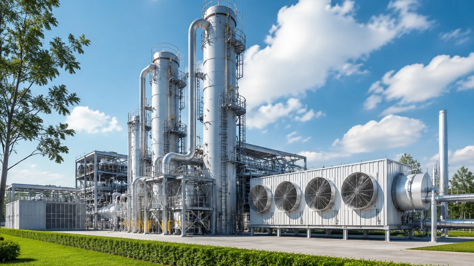
Carbon capture machines, often referred to as Carbon Capture, Utilization, and Storage (CCUS) systems, represent a critical frontier in industrial decarbonization. These complex engineering systems are designed to isolate carbon dioxide (CO2) from industrial flue gases or directly from the atmosphere, preventing it from contributing to the greenhouse effect. For plant engineers and project managers, the efficiency of these machines depends heavily on the precise control of fluid dynamics, chemical solvents, and phase separations.
In the context of industrial automation, the reliability of carbon capture machines is inextricably linked to the accuracy of the instrumentation monitoring them. Level measurement, in particular, is a foundational requirement for the safe and continuous operation of the absorbers, regenerators, and storage tanks that comprise a modern carbon capture facility.
Introduction to Carbon Capture Systems
Carbon capture machines operate through several distinct technological pathways, each requiring specific environmental controls. The most mature technology is post-combustion capture, which typically uses chemical solvents like amines to scrub CO2 from exhaust gases. Other methods include pre-combustion capture, where fuel is converted into a mixture of hydrogen and CO2 before burning, and oxy-fuel combustion, which burns fuel in pure oxygen to produce a concentrated CO2 stream.
Regardless of the specific method, these machines involve the large-scale handling of liquids and gases. For instance, in an amine-based system, the "rich" amine (loaded with CO2) and "lean" amine (stripped of CO2) must be carefully managed within tall absorption columns and flash tanks. Monitoring the levels within these vessels is not merely a matter of inventory; it is essential for preventing pump cavitation, ensuring optimal contact time between gas and liquid, and avoiding hazardous overfill conditions.
Fundamental Technologies in Carbon Capture Machines
To understand the instrumentation requirements, one must first look at the core components of carbon capture machines:
1. Absorber Columns: Large towers where flue gas meets a liquid solvent. Level sensors here monitor the liquid sump to ensure the solvent is circulating correctly.
2. Regenerators (Strippers): Heat is applied here to separate the CO2 from the solvent. This involves high temperatures (often above 100°C) and corrosive environments.
3. Separators and Flash Tanks: These vessels manage phase changes. Maintaining a stable liquid level is vital to prevent gas carry-over into liquid lines or liquid carry-over into gas compressors.
4. Compression and Liquefaction Units: Captured CO2 is compressed into a supercritical or liquid state for transport. This requires high-pressure vessels where level measurement must account for changing gas densities.
Principles of Level Measurement for CCUS Applications
Before selecting instrumentation for carbon capture machines, it is necessary to understand the physics behind the measurement. In the industrial sector, several principles are commonly employed, each with specific advantages for CO2 processing.
Radar Level Measurement (ToF)
Radar sensors operate on the Time-of-Flight (ToF) principle. A sensor emits high-frequency electromagnetic pulses (typically in the 26 GHz or 80 GHz range) that travel to the product surface and reflect back. The distance is calculated based on the time interval.
* Non-contact Radar: Ideal for corrosive solvents as the sensor does not touch the liquid.
* Guided Wave Radar (GWR): Uses a probe to guide the signal. This is highly effective in vessels with internal obstructions or where low dielectric constants (like liquid CO2) make non-contact measurement difficult.
Ultrasonic Level Measurement
Ultrasonic sensors emit mechanical sound waves. The time taken for the echo to return from the surface determines the level. While cost-effective, these are generally limited to atmospheric tanks and may be affected by temperature gradients or heavy foam, which is common in amine scrubbing.
Hydrostatic Level Measurement
This principle relies on the relationship between the height of a liquid column and the pressure it exerts at the base ($P = \rho \cdot g \cdot h$). By measuring the pressure and knowing the liquid density ($\rho$), the height ($h$) can be determined. In carbon capture machines, this is often used in solvent storage tanks, though density compensation is required if temperatures fluctuate.
Magnetic Level Gauges
These are bypass chambers mounted to the side of a vessel. A float containing a magnet moves with the liquid level, flipping mechanical flags or interacting with a reed-chain transmitter. They provide a high-visibility local display that requires no power, serving as a critical safety backup for electronic systems.
Selection Criteria for Level Instruments in Carbon Capture
When outfitting carbon capture machines, engineers must evaluate instruments based on the chemical and physical properties of the process. The following table provides a general guideline for technology selection in a typical CCUS plant.
| Application | Typical Conditions | Recommended Technology | Why? |
| :— | :— | :— | :— |
| Amine Absorber Sump | High humidity, foaming, ambient pressure | 80 GHz Non-contact Radar | Penetrates foam and vapor better than ultrasonic. |
| Regenerator/Stripper | High temp (120°C+), corrosive amines | Guided Wave Radar (GWR) | Probe materials (PTFE/316L) resist corrosion; signal is stable at high temps. |
| Liquid CO2 Storage | High pressure (20-70 bar), low temp | Magnetic Level Gauge / GWR | Magnetic gauges handle high pressure safely; GWR provides digital accuracy. |
| Solvent Makeup Tanks | Ambient temp, chemical storage | Hydrostatic Transmitter | Reliable, cost-effective for static density liquids. |
| Separator Vessels | Turbulent surface, gas/liquid interface | Guided Wave Radar | Direct contact ensures signal return despite turbulence. |
For a comprehensive review of available industrial instrumentation suited for these applications, visit the Main Page of the Welk product catalog.
Key Challenges: Foaming and Pressure
One of the most significant hurdles in carbon capture machines is the tendency of chemical solvents to foam. In post-combustion capture, impurities in the flue gas can react with the amine, creating a thick layer of foam on the liquid surface.
Standard ultrasonic sensors often fail in these conditions because the foam absorbs the sound waves. Radar technology is more resilient, but even then, high-frequency 80 GHz radar is preferred over lower frequencies because its narrow beam can be focused to avoid reflections from foam buildup on vessel walls. In extreme cases, a mechanical float-based system or a displacement transmitter may be used, as these rely on buoyancy rather than surface reflection.
Another challenge is the supercritical state of CO2. When CO2 is compressed for transport, it reaches a state where the distinction between liquid and gas disappears. Level measurement in these vessels requires specialized sensors that can handle pressures exceeding 74 bar (7.4 MPa) and temperatures where the dielectric constant of the fluid changes rapidly.
Installation and Maintenance Considerations
Proper installation is as important as technology selection for the longevity of carbon capture machines.
1. Nozzle Geometry: For radar installations, the height and diameter of the mounting nozzle must be considered to prevent "ringing" or false reflections. A nozzle that is too long and narrow can interfere with the signal.
2. Material Compatibility: Amine solutions are notoriously corrosive to certain metals. All wetted parts of the level meter should be constructed from 316L Stainless Steel, Hastelloy, or coated with PTFE/PFA.
3. Stilling Wells: In vessels with high agitation or heavy foam, installing the level sensor inside a stilling well (a vertical pipe) can provide a calm surface for measurement.
4. Calibration: Hydrostatic sensors must be calibrated for the specific gravity of the solvent. If the concentration of the amine changes, the level reading will drift unless density compensation is integrated into the control loop.
Limitations of Current Technologies
While modern instrumentation is highly advanced, no single technology is a "silver bullet" for all carbon capture machines.
* Ultrasonic is limited by vacuum conditions (sound cannot travel in a vacuum) and high-pressure environments where the speed of sound changes.
* Non-contact Radar can be challenged by very low dielectric constants ($ε_r < 1.4$), though liquid CO2 usually falls just above this threshold.
* Hydrostatic sensors are sensitive to changes in vessel pressure. In pressurized carbon capture tanks, a differential pressure (DP) setup is required to subtract the top-side gas pressure from the total bottom pressure.
Frequently Asked Questions (FAQs)
Q: Can I use the same level meter for both solvent storage and the CO2 stripper?
A: Generally, no. The solvent storage tank is usually at ambient temperature and pressure, where a simple hydrostatic or ultrasonic sensor suffices. The stripper operates at high temperatures and involves corrosive vapors, necessitating a high-temperature rated Guided Wave Radar or a Magnetic Level Gauge with a high-pressure rating.
Q: How does foaming affect the accuracy of level measurement in carbon capture?
A: Foaming creates a "false surface." Ultrasonic sensors may measure the top of the foam or lose the signal entirely. Radar is better at penetrating foam, but thick, dense foam can still cause a signal attenuation. Using a Guided Wave Radar with a coaxial probe is often the best solution for foamy applications.
Q: What is the maintenance cycle for level sensors in an amine-based carbon capture machine?
A: Due to the potential for chemical scaling and corrosion, wetted sensors should be inspected every 6 to 12 months. Non-contact sensors typically require less maintenance as they do not touch the process media, but the antenna should still be checked for buildup from condensed vapors.
Q: Is liquid CO2 difficult to measure?
A: Yes, because it has a low dielectric constant and is often stored at high pressures. Guided Wave Radar is the industry standard for this application because the probe helps concentrate the signal, ensuring a reliable reflection even from "low-reflective" liquids like CO2.
By carefully matching the level measurement technology to the specific demands of each stage within carbon capture machines, operators can ensure higher uptime, better solvent management, and safer overall plant performance. As the global push for net-zero emissions accelerates, the role of precise, reliable instrumentation in these systems will only become more vital.