Tmt162
Tmt162
In the landscape of industrial automation and process control, the accuracy of field instrumentation determines the safety, efficiency, and quality of the entire production line. Among the critical components used to monitor process conditions, the TMT162 stands out as a high-performance temperature field transmitter designed to bridge the gap between raw sensor data and control system requirements. While temperature measurement is a distinct discipline, its integration with level measurement systems—such as those found on the Main Page of industrial instrumentation providers—is essential for comprehensive process oversight.
This guide explores the technical foundations of the TMT162, its role in modern industrial environments, and how engineers can effectively select and install these devices to ensure long-term reliability.
Measurement Principles and Technology
The TMT162 operates as a signal converter and transmitter. Its primary function is to receive low-level signals from temperature sensors—typically Resistance Temperature Detectors (RTDs) or Thermocouples (TC)—and convert them into a stable, standardized industrial signal, such as 4-20 mA with HART protocol, Foundation Fieldbus, or PROFIBUS PA.
Signal Conversion and Linearization
Temperature sensors do not produce a linear output. For instance, the resistance of a Pt100 sensor changes according to a specific curve defined by international standards (IEC 60751). The TMT162 utilizes an internal microprocessor to perform high-precision linearization. By applying mathematical algorithms to the incoming millivolt (TC) or ohmic (RTD) signals, the transmitter ensures that the output signal accurately reflects the actual temperature of the process medium.
Dual-Compartment Housing
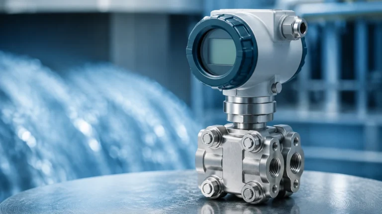
One of the defining features of field transmitters like the TMT162 is the dual-compartment housing. This design separates the electronics from the terminal compartment. This physical barrier protects the sensitive microprocessor and display from environmental moisture, dust, and potential corrosive gases during wiring or maintenance, significantly increasing the device's Mean Time Between Failures (MTBF).
Integration with Level Measurement Systems
In many B2B industrial applications, temperature measurement is not an isolated requirement but a necessary variable for accurate level detection. This is particularly true in the chemical, oil and gas, and water treatment sectors served by Welk.
Temperature Compensation in Hydrostatic Level
Hydrostatic level transmitters measure the pressure exerted by a liquid column to determine height. However, the density of a liquid changes with temperature. If the temperature of a storage tank fluctuates significantly, a static density value will lead to level measurement errors. By integrating a TMT162 temperature transmitter into the control loop, the PLC or DCS can calculate real-time density corrections, ensuring that the level readings remains precise regardless of thermal expansion or contraction.
Radar and Ultrasonic Considerations
While radar level meters are largely unaffected by gas-phase temperature changes, ultrasonic sensors rely on the speed of sound, which is highly temperature-dependent. In applications where an ultrasonic sensor is used, a TMT162 can provide high-accuracy ambient or vapor-space temperature data to the transmitter's processing unit to adjust the distance calculation. For a broader look at how these technologies interact, engineers often consult the Main Page for integrated solution architectures.
Key Evaluation Criteria and Selection
Selecting the right configuration for a TMT162 requires an analysis of both the process requirements and the environmental conditions. Use the following table as a baseline for selection:
| Criteria | Specification Options | Application Context |
| :— | :— | :— |
| Input Type | Pt100, Pt500, Pt1000, TC (J, K, T, E, R, S, B, N) | Choose based on required temperature range and sensitivity. |
| Output Signal | 4-20 mA HART, PROFIBUS PA, Foundation Fieldbus | Must match the existing control system architecture. |
| Housing Material | Aluminum (powder-coated) or Stainless Steel (316L) | Stainless steel is mandatory for offshore or highly corrosive chemical environments. |
| Accuracy Class | Typically < 0.1°C for RTD inputs | High precision is required for custody transfer or sensitive chemical reactions. |
| Certifications | ATEX, FM, CSA, SIL 2/3 | Required for hazardous areas and safety-instrumented systems. |
Housing and Display Options
For field-mounted applications, a large, backlit digital display is often preferred. This allows field operators to verify process values without needing to return to the control room. The TMT162 typically offers a bar graph display for a quick visual reference of the 4-20 mA loop percentage, which is invaluable during commissioning and troubleshooting.
Installation Guidelines and Best Practices
Proper installation of a TMT162 is as critical as the device's internal specifications. Failure to follow engineering best practices can result in signal noise, measurement lag, or premature hardware failure.
1. Thermowell Selection: The transmitter is usually coupled with a temperature sensor protected by a thermowell. The thermowell must be sized to withstand the flow-induced vibration and pressure of the process. The insertion length should be at least 10 times the diameter of the protection tube to minimize heat conduction errors.
2. Mounting Location: While the TMT162 is designed for field use, it should be mounted in a location that minimizes exposure to extreme vibration. If the process vessel vibrates excessively, consider remote mounting the transmitter using a bracket and a shielded cable to connect to the sensor.
3. Wiring and Grounding: Use twisted, shielded pairs for the 4-20 mA loop. Ensure the shield is grounded at one end only (usually the control room side) to prevent ground loops. The TMT162's internal grounding terminal should be connected to the local plant ground for lightning and surge protection.
4. Cable Glands: Always use certified cable glands that match the housing's ingress protection (IP) rating (e.g., IP67). In hazardous areas, ensure the glands meet the specific Ex d or Ex ia requirements of the zone.

Common Risks and Limitations
Despite its robust design, the TMT162 and similar field transmitters face specific risks in industrial environments:
* Sensor Drift: Over time, RTDs and thermocouples can drift from their calibrated values. Regular loop checks and sensor calibration are necessary to maintain system integrity.
* Ambient Temperature Effects: Although the TMT162 has internal temperature compensation for its own electronics, extreme ambient heat (above 85°C) can cause electronic failure. In such cases, sunshades or remote mounting are required.
* Galvanic Isolation: In environments with high electromagnetic interference (EMI), ensure the transmitter provides sufficient galvanic isolation (typically 2 kV AC) between the input and output. This prevents electrical noise from the sensor side from corrupting the control signal.
* Corrosion of Terminals: If the housing is not sealed correctly, moisture ingress can lead to terminal corrosion. This increases resistance in the loop and can cause erratic readings or complete signal loss.
Frequently Asked Questions (FAQs)
Q: Can the TMT162 handle two sensor inputs simultaneously?
Yes, many versions of the TMT162 support dual-channel input. This allows for sensor backup (automatic switchover if one sensor fails) or differential temperature measurement, which is useful in heat exchanger monitoring.
Q: What is the difference between a head-mounted transmitter and a field-mounted transmitter like the TMT162?
A head-mounted transmitter is small and fits inside the connection head of the sensor. A field-mounted transmitter like the TMT162 is larger, features a robust housing, often includes a display, and is designed for harsher environments where local visualization is required.
Q: Is the TMT162 compatible with older PLC systems?
As long as the PLC supports a standard 4-20 mA analog input, the TMT162 is compatible. For digital integration, the PLC must support the specific protocol (HART, etc.) configured on the transmitter.
Q: How often should the TMT162 be calibrated?
While the electronics are very stable, it is standard practice to verify the entire measurement loop (sensor + transmitter) annually. In critical safety applications (SIL-rated), the proof-test interval may be shorter as defined by the safety manual.
Conclusion and Technical Confirmation
The TMT162 represents a vital link in the chain of industrial process control. By converting sensitive temperature data into robust digital or analog signals, it enables precise control over complex systems. For engineers managing bulk liquid storage or chemical processing, understanding how temperature data interacts with level measurement is paramount.
Before finalizing a specification, project teams should confirm the chemical compatibility of the housing with the local atmosphere and ensure the chosen communication protocol is fully supported by the site's existing infrastructure. For comprehensive details on integrating these transmitters with level measurement hardware, visiting the Main Page provides access to technical data sheets and application support designed for professional engineering requirements.