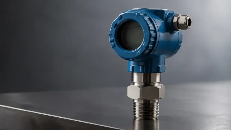
Transmitter Pressure Differential
Transmitter Pressure Differential
Differential pressure (DP) measurement is one of the most established and versatile technologies used in modern industrial process control. A transmitter pressure differential system works by measuring the difference in pressure between two distinct points in a process. While these instruments are frequently used for flow measurement across an orifice plate, their application in liquid level measurement is critical for industries ranging from chemical processing and oil and gas to water treatment and industrial automation.
For engineers and plant operators, understanding the mechanics of a transmitter pressure differential setup is essential for ensuring accuracy, safety, and long-term reliability. As a professional manufacturer, Welk provides a range of hydrostatic and differential pressure solutions designed to meet the rigorous demands of these sectors. This guide explores the principles, selection criteria, and installation requirements for DP level measurement.
Measurement Principles of DP Transmitters
The fundamental principle behind using a transmitter pressure differential for level measurement is hydrostatic pressure. According to Pascal’s Law, the pressure exerted by a static liquid column is directly proportional to the height of the liquid and its density. The formula is expressed as:
P = ρ × g × h
Where:
* P is the hydrostatic pressure.
* ρ (rho) is the density of the liquid (kg/m³).
* g is the acceleration due to gravity (approximately 9.81 m/s²).
* h is the height of the liquid column (meters).
In a level measurement application, the DP transmitter measures the pressure at the bottom of the vessel. However, in many industrial scenarios, the vessel is pressurized. To isolate the pressure exerted solely by the liquid, the transmitter must subtract the internal vessel pressure (the "blanket" pressure) from the total pressure measured at the bottom. This is achieved by connecting the "High Pressure" (HP) side of the transmitter to the bottom of the tank and the "Low Pressure" (LP) side to the vapor space at the top of the tank. The resulting transmitter pressure differential represents the true liquid level, independent of the internal tank pressure.
Open Tank vs. Closed Tank Applications
The configuration of a transmitter pressure differential system depends heavily on whether the vessel is open to the atmosphere or sealed and pressurized.
Open Tank Measurement
In an open tank, the surface of the liquid is exposed to atmospheric pressure. In this case, the LP side of the transmitter is simply vented to the atmosphere. The HP side is connected to the process at the minimum level point. The transmitter measures the pressure of the liquid column against the ambient air. This is the simplest form of hydrostatic level measurement.
Closed Tank Measurement
In closed tanks, the space above the liquid may contain pressurized gas or steam. If the LP side were vented to the atmosphere, the transmitter would include the gas pressure in its reading, leading to a massive error. Instead, the LP side is piped to the top of the vessel. There are two primary methods for this connection:
1. Dry Leg: Used when the gas above the liquid will not condense at ambient temperatures. The pipe (leg) remains filled with gas.
2. Wet Leg: Used when the gas is likely to condense (e.g., steam). The LP leg is intentionally filled with a reference liquid (often the process fluid or a stable condensate) to prevent erratic readings caused by random condensation. The weight of this liquid column must be accounted for during calibration through "zero suppression."
Remote Diaphragm Seals and Capillary Systems
In many B2B industrial applications, the process fluid is too corrosive, viscous, or hot to come into direct contact with the transmitter’s internal sensing diaphragm. In these instances, a transmitter pressure differential system utilizes remote diaphragm seals connected via capillaries.
These capillaries are thin tubes filled with a transmission fluid (such as silicone oil). The process pressure presses against a robust external diaphragm, which transfers the pressure through the fill fluid to the transmitter sensor. This setup is common in the chemical and food industries where hygienic requirements or extreme temperatures (exceeding 100°C) are present. When selecting these systems, it is vital to consider the thermal expansion of the fill fluid, as significant temperature swings can introduce small measurement offsets.
Technical Selection Criteria for DP Transmitters
Selecting the correct transmitter pressure differential instrument requires a detailed analysis of the process environment. Engineers should evaluate the following factors:
| Criteria | Description | Importance |
| :— | :— | :— |
| Pressure Range | The maximum and minimum expected DP based on liquid height and density. | Critical for resolution and safety. |
| Static Pressure | The total internal pressure of the vessel. | The transmitter must withstand the base pressure without shifting calibration. |
| Material Compatibility | Wetted parts (diaphragms, flanges) must resist corrosion. | Prevents premature failure in chemical apps. |
| Accuracy Class | Typically expressed as a percentage of the calibrated span (e.g., ±0.075%). | Essential for inventory control and billing. |
| Process Temperature | The temperature of the fluid at the point of contact. | Determines if remote seals or cooling elements are needed. |
| Output Signal | 4-20mA HART, Profibus, or Foundation Fieldbus. | Ensures compatibility with the existing PLC/DCS. |
For a comprehensive look at available hardware and technical support for these specifications, you may visit the Main Page of our product catalog.
Installation Best Practices
The reliability of a transmitter pressure differential reading is often determined by the quality of the installation rather than the instrument itself. Improperly installed impulse lines are the leading cause of measurement error.
1. Impulse Piping Slope: Impulse lines should always be sloped (at least 1:12 ratio). For gas applications, they should slope down toward the transmitter to allow condensate to drain back into the tank. For liquid applications, they should slope up toward the transmitter to allow gas bubbles to escape.
2. Manifold Valves: A 3-valve or 5-valve manifold should always be installed between the process and the transmitter. This allows for safe isolation, venting, and zero-checking without shutting down the entire process.
3. Environmental Protection: While industrial transmitters are rugged, protecting them from direct solar radiation or extreme vibration will extend the lifespan of the electronics and improve signal stability.
4. Mounting Position: The transmitter should ideally be mounted below the high-pressure tapping point for liquid service to ensure the impulse lines remain full. If the transmitter is mounted above the tapping point, a gas trap or specific calibration adjustments are required.

Calibration: Zero Elevation and Suppression
Calibration is the process of mapping the measured pressure to a 0-100% level scale. In many transmitter pressure differential installations, the transmitter is not physically located at the exact "zero" level of the tank.
* Zero Suppression: If the transmitter is mounted below the bottom of the tank, the HP impulse line will have a constant head of liquid even when the tank is empty. This constant pressure must be "suppressed" so the transmitter reads 0% at the actual tank bottom.
* Zero Elevation: In wet leg applications, the LP side has a constant head of liquid that is greater than the HP side when the tank is empty. This results in a negative differential pressure. The transmitter must be calibrated with a "zero elevation" to account for this negative offset.
Limitations and Common Challenges
While highly effective, transmitter pressure differential technology has specific limitations that must be managed:
* Density Sensitivity: Since DP transmitters measure mass/weight to infer level, any change in liquid density (caused by temperature fluctuations or changes in chemical composition) will result in a level error. If the density decreases, the level will appear lower than it actually is.
* Clogging: Impulse lines are susceptible to clogging if the process fluid contains solids or is prone to crystallization. In these cases, a flush-mounted diaphragm or a radar-based solution might be more appropriate.
* Gas Entrapment: Small air bubbles trapped in a liquid impulse line can compress and expand, causing "noisy" or inaccurate signals.
Comparison Table: DP vs. Other Technologies
To help in the selection process, the following table compares the transmitter pressure differential method with other common level measurement technologies.
| Technology | Best For | Main Advantage | Main Limitation |
| :— | :— | :— | :— |
| DP Transmitter | Pressurized tanks, high temp | Proven, versatile, cost-effective | Affected by density changes |
| Radar (Non-contact) | Corrosive, volatile liquids | No contact with media | High initial cost |
| Ultrasonic | Water/Wastewater | Easy installation | Affected by foam and vacuum |
| Magnetic Gauge | Visual local indication | No power required for visual | Mechanical moving parts |
Frequently Asked Questions (FAQs)
Q: Can a DP transmitter be used for interface measurement?
A: Yes. If two immiscible liquids (like oil and water) are in a tank, a transmitter pressure differential system can measure the interface level, provided the total level remains above the top tapping point and the densities of both liquids remain constant.
Q: How often should a transmitter pressure differential be calibrated?
A: While modern digital transmitters have excellent long-term stability, it is standard practice to perform a bench check or field verification every 12 to 24 months, depending on the criticality of the process.
Q: What happens if the LP leg of a dry leg system fills with liquid?
A: This will cause a significant measurement error, as the transmitter will subtract the weight of that liquid from the HP reading. The level will be reported as much lower than it actually is. This is why wet legs or remote seals are preferred in condensing environments.
Q: Are DP transmitters suitable for vacuum service?
A: Yes, but special care must be taken when selecting remote seals and fill fluids. Under deep vacuum, some fill fluids can outgas, causing the diaphragm to "balloon" and fail. Always specify vacuum service when ordering.
Conclusion
The transmitter pressure differential remains a primary choice for industrial level measurement due to its reliability and the depth of engineering knowledge surrounding its application. By carefully considering the vessel type, liquid characteristics, and installation geometry, engineers can implement a measurement solution that provides years of accurate data. For those seeking specific product configurations or OEM/ODM services for level measurement instruments, reviewing the technical options on the Main Page is a recommended next step in the procurement process.
Welk continues to support global industries with advanced technology and strict quality control, ensuring that whether you are managing a simple water tank or a complex chemical reactor, your level measurement is precise and cost-effective.