Tss Meters
Tss Meters
In industrial water treatment and process control, monitoring the concentration of solids in a liquid is a fundamental requirement for maintaining efficiency and regulatory compliance. Total Suspended Solids (TSS) represent the dry weight of particles trapped by a filter, typically measured in milligrams per liter (mg/L) or grams per liter (g/L). While laboratory gravimetric analysis remains the reference standard, modern industrial operations rely on online tss meters to provide real-time data for automated control systems.
Understanding the technology behind these instruments is essential for engineers and plant operators. This guide explores the measurement principles, selection criteria, and installation best practices for integrating tss meters into industrial workflows, particularly in environments where they complement other process instruments such as those found on the Main Page of industrial instrumentation providers.
Principles of TSS Measurement
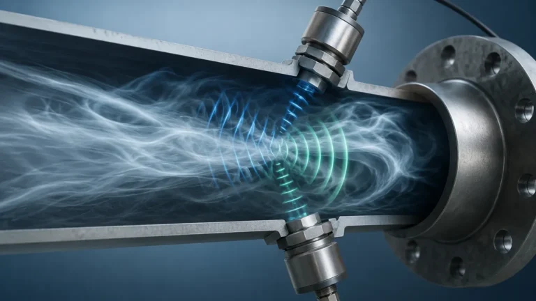
Unlike level measurement, which uses time-of-flight or hydrostatic pressure, TSS measurement is primarily optical. Online tss meters utilize the interaction between light and suspended particles to estimate concentration. The choice of optical principle depends heavily on the expected concentration range and the nature of the solids.
1. Light Scattering (Nephelometry)
This method measures the light scattered by particles at a specific angle, usually 90 degrees, relative to the incident light beam. It is highly sensitive and is the standard for low-concentration applications, often referred to as turbidity measurement. In these systems, a light source (typically infrared to minimize color interference) emits a beam into the fluid, and a photo-detector captures the scattered light. The intensity of the scattered light is proportional to the number of particles in the path.
2. Light Absorption (Transmission)
For medium to high concentrations of suspended solids, the scattering effect becomes non-linear due to multiple scattering events. In these cases, tss meters measure the attenuation of light as it passes through the sample. The detector is placed 180 degrees from the light source. As the concentration of solids increases, more light is absorbed or blocked, and the signal reaching the detector decreases. This follows the Beer-Lambert law, though it requires empirical calibration for specific types of sludge or waste.
3. Backscattering
In extremely high-concentration environments, such as primary sludge or thickened sludge (where concentrations can exceed 50 g/L), light cannot penetrate the medium effectively. Backscatter sensors measure the light reflected back at an angle greater than 90 degrees (often around 135 degrees). This method is robust for thick slurries where traditional transmission would fail.
4. Multi-Beam Ratio Method
Advanced tss meters often use multiple light sources and detectors to compensate for sensor fouling and electronic drift. by comparing the ratios of signals from different paths, the instrument can provide a more stable reading over time, reducing the frequency of manual cleaning and recalibration.
Key Evaluation and Selection Criteria
Selecting the correct instrument requires a thorough understanding of the process fluid. A sensor designed for clean effluent will fail rapidly if placed in an aeration tank or a chemical slurry line.
Concentration Range
The most critical factor is the expected TSS range. Meters are typically categorized into low (0–1,000 mg/L), medium (up to 10,000 mg/L), and high (up to 100,000 mg/L or more) ranges. Choosing a sensor with an inappropriate range leads to saturation or poor resolution.
Particle Characteristics
The size, shape, and color of the suspended particles affect light scattering. For example, dark-colored particles absorb more light than they scatter, which can lead to inaccuracies in nephelometric sensors. If the particle size distribution changes significantly over time, the meter may require frequent recalibration against laboratory samples.
Process Environment
Consider the temperature, pressure, and chemical compatibility of the sensor housing. In corrosive chemical processing or high-temperature industrial discharge, stainless steel or specialized plastic bodies (such as PVC or PEEK) are necessary. Furthermore, in applications involving grease or biological growth, a sensor with an integrated cleaning system is mandatory.
Selection Table for Common Applications
| Application | Typical Range | Recommended Principle | Sensor Type |
| :— | :— | :— | :— |
| Potable Water / Effluent | 0–100 mg/L | 90° Scattering | Submersible Probe |
| Aeration Tanks (MLSS) | 2,000–5,000 mg/L | Absorption / Ratio | Submersible Probe |
| Return Activated Sludge | 5,000–15,000 mg/L | Absorption | Pipe-Mounted / Bypass |
| Primary Sludge | 2%–10% Solids | Backscatter | High-Density Probe |
| Chemical Slurries | Variable | Absorption | Flow-through Cell |
Installation Considerations and Best Practices
The accuracy of tss meters is often more dependent on the installation location than the instrument's specifications. Unlike hydrostatic level transmitters that can be mounted at the bottom of a tank, TSS sensors must be placed where the fluid is representative of the entire process.
1. Flow Velocity and Turbulence
To prevent solids from settling on the sensor face, a minimum flow velocity is usually required (typically >0.5 m/s). However, excessive turbulence can introduce air bubbles. Air bubbles are highly reflective and will be interpreted by the meter as suspended solids, leading to false high readings. In pressurized pipes, installing the sensor on the side (3 o'clock or 9 o'clock position) helps avoid both settled sediment at the bottom and air pockets at the top.
2. Avoiding Ambient Light
Optical sensors can be affected by ambient sunlight, especially in open channels or shallow tanks. Sensors should be submerged at a sufficient depth (at least 30 cm) or shielded with a weather cover to ensure that only the internal light source is measured.
3. Mounting Orientation
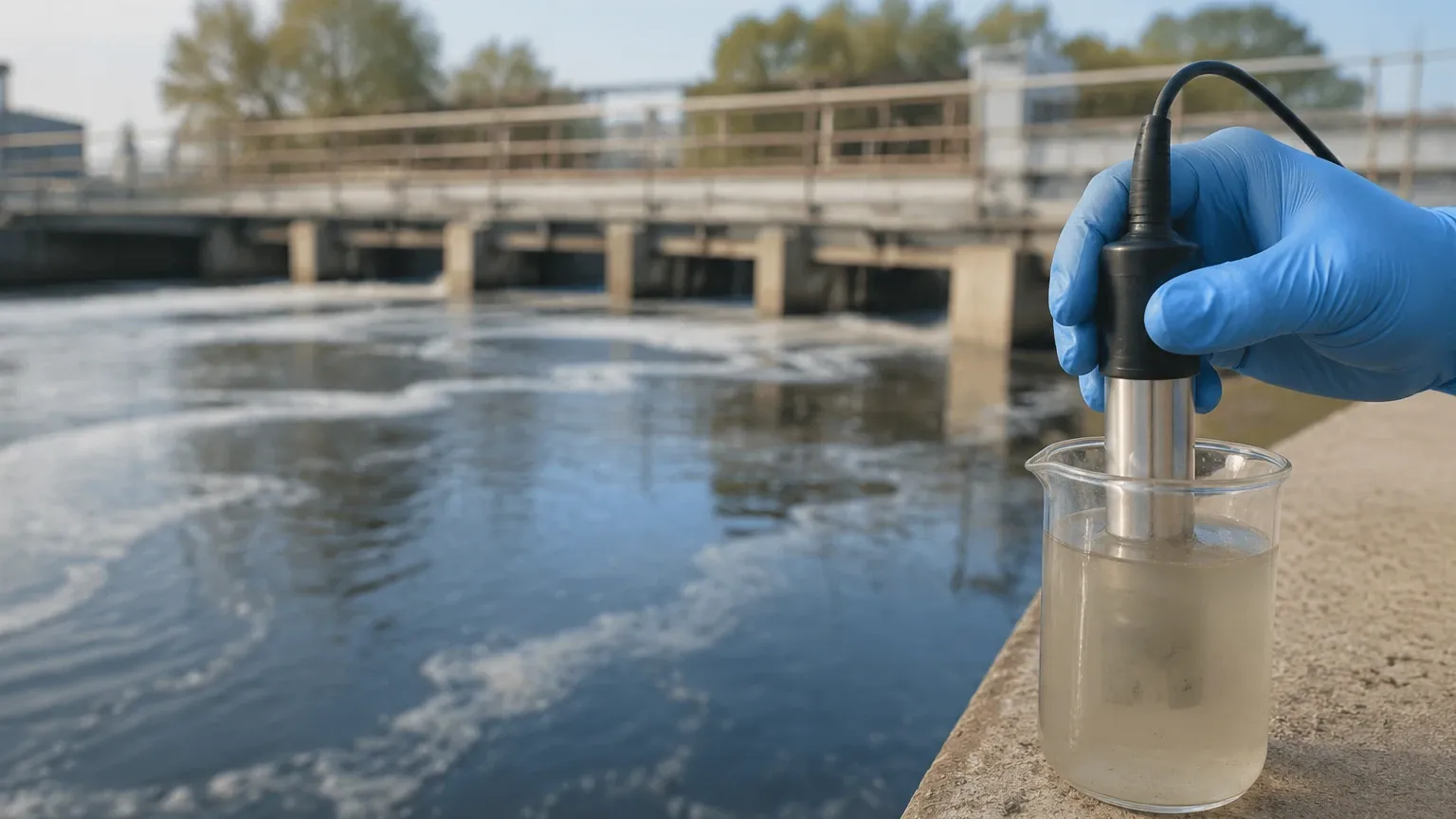
Submersible probes should be mounted at an angle (typically 45 degrees) against the flow. This orientation allows the moving fluid to naturally "wash" the sensor face, reducing the rate of debris accumulation. In pipe installations, ensure the pipe is always full; a partially full pipe will cause the sensor to read the air-liquid interface, resulting in errors.
4. Integration with Level Systems
In many tank management scenarios, TSS data is used in conjunction with level data. For instance, in a clarifier, a radar level meter or ultrasonic sensor might monitor the water surface level while a TSS probe monitors the sludge blanket or effluent quality. Coordination between these instruments ensures that pumps are not run dry and that discharge limits are not exceeded. For more information on integrating these technologies, professionals often consult the Main Page for comprehensive measurement solutions.
Common Risks and Limitations
While online tss meters are powerful tools, they are not "set and forget" devices. Awareness of their limitations prevents operational failures.
* Fouling: This is the most common cause of error. Even a thin film of biofilm or scale can significantly alter light transmission. Automatic cleaning systems (wipers, ultrasonic cleaners, or air-blast systems) are highly recommended for wastewater applications.
* Color Changes: If the process fluid changes color (e.g., in textile or dye manufacturing), the absorption characteristics change. Unless the meter uses a multi-wavelength compensation technique, the TSS reading will drift even if the actual solids concentration remains constant.
* Calibration Drift: Optical components age over time. Regular verification against a laboratory gravimetric test is necessary. Most industrial users perform a "zero" calibration with deionized water and a "span" calibration using a representative process sample.
* Representative Sampling: A TSS meter only measures the small volume of liquid directly in front of the sensor. If the tank is not well-mixed, the reading may not reflect the average concentration of the entire vessel.
Maintenance Guidance
A proactive maintenance schedule ensures the longevity and reliability of the instrument.
1. Weekly Inspection: Visually check the sensor for signs of physical damage or heavy fouling. Verify that the cleaning mechanism (if equipped) is moving freely.
2. Monthly Verification: Compare the online reading with a manual grab sample analyzed in a lab. If the deviation exceeds 10%, a field calibration is likely required.
3. Quarterly Cleaning: Manually clean the optical windows with a soft cloth and mild detergent. Avoid abrasive materials that could scratch the glass or plastic, as scratches will scatter light and cause permanent offsets.
4. Annual Service: Replace seals, O-rings, and wiper blades. Check the integrity of the cable entry to prevent moisture ingress, which is a leading cause of electronic failure in submersible probes.
Frequently Asked Questions (FAQs)
Q: What is the difference between Turbidity and TSS?
A: Turbidity is an optical property—how much light is scattered by the water. TSS is a measure of the actual mass of solids. While they are related, the correlation changes if the particle size or density changes. TSS meters are calibrated to output mass units (mg/L), whereas turbidity meters output NTU (Nephelometric Turbidity Units).
Q: Can a TSS meter measure dissolved solids (TDS)?
A: No. TSS meters detect particles that are physically suspended. Dissolved solids, such as salts and minerals, do not scatter or block light in the same way and must be measured using conductivity or laboratory evaporation methods.
Q: How often should I calibrate my TSS meter?
A: Initially, calibration should be checked weekly. Once the correlation between the optical signal and the specific process sludge is established and the sensor proves stable, the interval can often be extended to monthly or quarterly, depending on the criticality of the measurement.
Q: Can these sensors be used in hazardous areas?
A: Yes, many tss meters are available with ATEX or IECEx certifications for use in explosive atmospheres. These models typically feature intrinsically safe electronics or explosion-proof enclosures.
By carefully matching the measurement principle to the specific concentration and environmental conditions of the application, engineers can implement a robust monitoring solution. When paired with reliable level measurement from the Main Page, online TSS monitoring provides the essential data needed for optimized industrial process control.