Gauge Pressure Sensor
Gauge Pressure Sensor
In the realm of industrial instrumentation, the gauge pressure sensor stands as a fundamental component for monitoring and controlling process variables. Whether it is used for measuring the pressure of compressed air lines or determining the liquid level in an open storage tank through hydrostatic principles, understanding the mechanics and selection criteria of these devices is essential for process engineers and plant managers.
As a professional manufacturer of industrial level measurement instruments, Welk provides a range of solutions that leverage gauge pressure technology. This guide serves as a practical engineering reference for choosing and implementing gauge pressure sensors across various industrial environments, from water treatment facilities to complex chemical processing plants.
Understanding the Measurement Principle
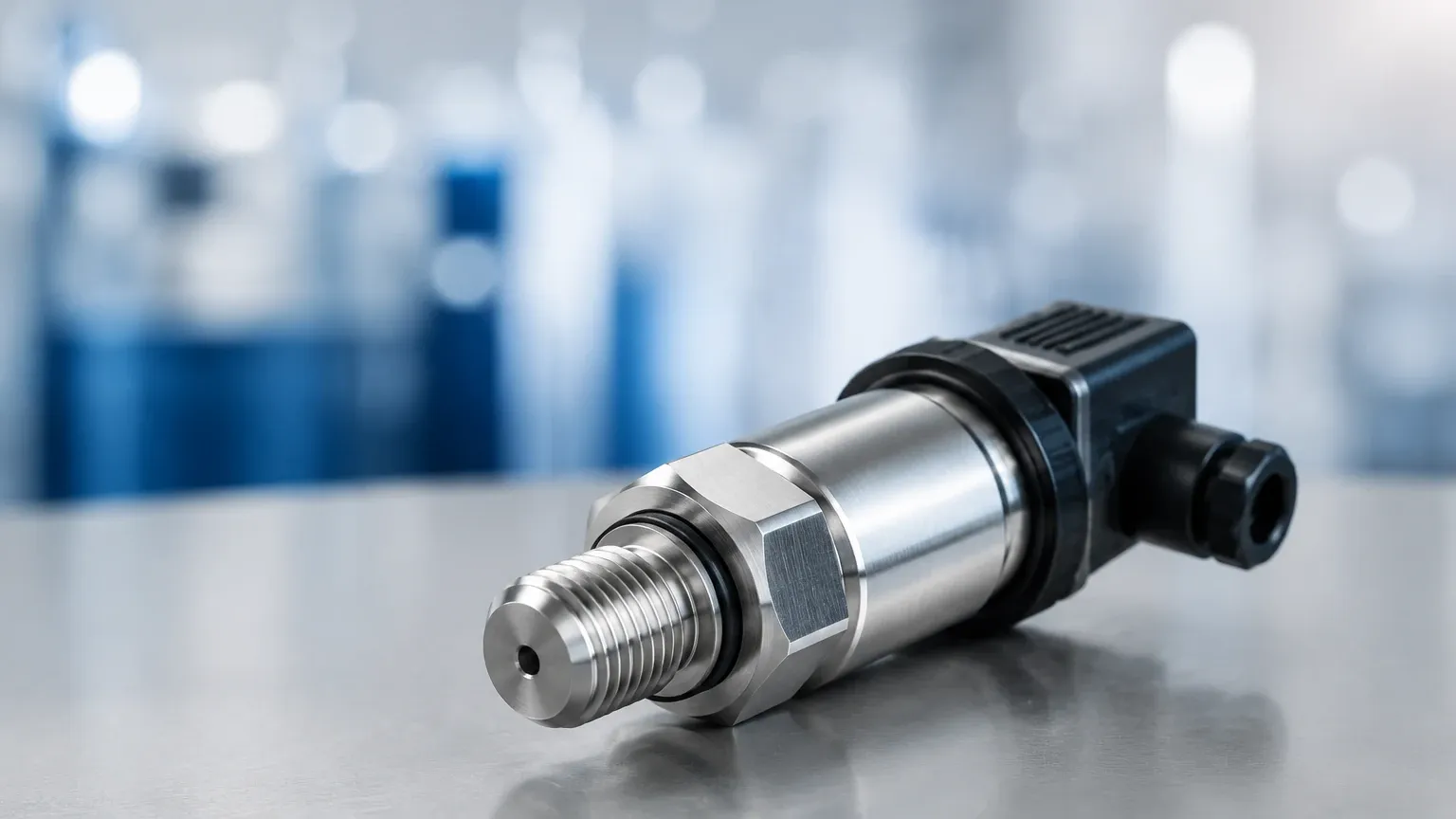
A gauge pressure sensor measures pressure relative to the current atmospheric pressure. Unlike an absolute pressure sensor, which measures against a perfect vacuum, or a differential pressure sensor, which measures the difference between two distinct process points, the gauge sensor uses the local ambient pressure as its zero point.
The Reference Pressure
The defining characteristic of a gauge pressure sensor is its reference to the atmosphere. The back side of the sensing diaphragm is exposed to the ambient air through a vent hole or a specialized breathing tube (often integrated into the signal cable). This design ensures that any changes in local barometric pressure—caused by weather patterns or changes in altitude—are applied to both sides of the diaphragm simultaneously. Consequently, the sensor only reports the pressure exerted by the process medium itself.
Sensing Technologies
Several physical principles are employed to convert mechanical pressure into an electrical signal:
1. Piezoresistive Sensors: These utilize a silicon or metallic diaphragm with integrated strain gauges. When pressure is applied, the diaphragm deforms, changing the electrical resistance of the gauges. This is one of the most common technologies due to its high sensitivity and stability.
2. Ceramic Thick Film Sensors: A ceramic diaphragm is used for its excellent chemical resistance. The deformation is measured via a resistive bridge printed on the ceramic. These are ideal for aggressive media where stainless steel might fail.
3. Capacitive Sensors: These measure the change in electrical capacitance between a flexible sensing diaphragm and a fixed plate. Capacitive sensors are known for their high accuracy and ability to measure very low pressure ranges (e.g., a few millibars).
The Relationship Between Gauge Pressure and Level Measurement
One of the most frequent applications for a gauge pressure sensor in industrial automation is hydrostatic level measurement. For any liquid in an open-to-atmosphere tank, the pressure at the bottom of the tank is directly proportional to the height of the liquid column above it.
The Hydrostatic Formula
The relationship is defined by the formula:
$$P = \rho \cdot g \cdot h$$
Where:
* P is the hydrostatic pressure (measured by the gauge pressure sensor).
* ρ (rho) is the density of the liquid (kg/m³).
* g is the acceleration due to gravity (approximately 9.81 m/s²).
* h is the height of the liquid (meters).
Because the sensor is vented to the atmosphere, it ignores the atmospheric pressure pushing down on the surface of the liquid, providing an accurate reading of the liquid level based solely on the weight of the fluid. This technology is widely utilized in the Main Page of industrial level monitoring strategies for reservoirs, wells, and chemical vats.
Key Evaluation Criteria for Selection
Selecting the right gauge pressure sensor requires a detailed analysis of the process environment. Engineers must confirm several technical parameters before procurement to ensure long-term reliability.
Pressure Range and Overpressure Rating
The nominal range should be selected so that the typical operating pressure falls within 50% to 75% of the sensor's full-scale value. However, it is equally important to check the overpressure rating. In systems where water hammer or pump surges occur, a sensor with a high overpressure limit (e.g., 2x or 3x the nominal range) is necessary to prevent diaphragm rupture.
Material Compatibility (Wetted Parts)
The material of the diaphragm and the process connection must be compatible with the media.
* 316L Stainless Steel: Standard for water and non-corrosive oils.
* Hastelloy C or Tantalum: Required for highly corrosive acids or chlorides.
* Ceramic (Al2O3): Excellent for abrasive slurries or aggressive chemicals where metals might leach.
Accuracy and Total Error Band
Accuracy is often stated as a percentage of the Full Scale (FS). In B2B applications, standard accuracies range from 0.5% FS to 0.1% FS. It is important to consider the "Total Error Band," which includes the effects of temperature shifts, linearity, and hysteresis over the entire operating temperature range.
Output Signals and Communication
Modern industrial automation relies on standardized signals for integration into PLC or SCADA systems:
* 4-20 mA: The industry standard for long-distance transmission with high noise immunity.
* HART Protocol: Allows for digital communication over the 4-20 mA loop for remote configuration and diagnostics.
* RS485/Modbus: Common in digital networks and IoT-enabled monitoring systems.
Selection Table for Industrial Applications
| Application | Recommended Diaphragm | Typical Range | Key Consideration |
| :— | :— | :— | :— |
| Potable Water Storage | 316L Stainless Steel | 0–2 bar (20m H2O) | Food-grade oil filling |
| Wastewater Sump | Ceramic or 316L with PTFE | 0–1 bar (10m H2O) | Clogging resistance |
| Chemical Dosing Tank | Hastelloy C or Ceramic | 0–500 mbar | Chemical compatibility |
| Hydraulic Systems | Stainless Steel | 0–400 bar | High overpressure protection |
| Fuel Oil Tanks | 316L Stainless Steel | 0–2.5 bar | Explosion-proof (ATEX/IECEx) |
Installation Considerations
Proper installation is as critical as sensor selection. A perfectly calibrated gauge pressure sensor will provide inaccurate data if installed incorrectly.
Venting and Moisture Protection
Since a gauge pressure sensor must "breathe," the vent path must remain unobstructed. For submersible sensors, the vent tube is usually located inside the cable. This tube must terminate in a dry environment, often using a localized junction box with a desiccant filter to prevent moisture from entering the tube. If water vapor enters the vent tube and condenses, it can create a capillary effect that blocks the reference pressure or, worse, corrodes the internal electronics.
Mounting Position
For liquid level applications, the sensor should be mounted at a point where the liquid is relatively static. Avoid placing the sensor directly in the path of an inflow pipe or near an agitator, as the kinetic energy of the moving fluid (dynamic pressure) will add to the hydrostatic pressure, causing a false high-level reading. If turbulence is unavoidable, the use of a stilling well (a perforated pipe) is recommended to dampen the fluid movement.
Temperature Gradients
While most high-quality sensors include internal temperature compensation, extreme temperature gradients can still cause zero-point drift. In outdoor installations, shielding the sensor from direct sunlight can improve long-term stability.
Common Risks and Limitations
Despite their versatility, gauge pressure sensors have specific limitations that engineers must account for in their designs.
1. Pressurized Tanks: A standard gauge pressure sensor cannot measure the liquid level in a pressurized vessel (such as a boiler or a pressurized gas storage tank). In these cases, the internal gas pressure would be added to the liquid pressure, resulting in an incorrect reading. A differential pressure sensor is required for such applications.
2. Vacuum Conditions: Most gauge sensors are designed to measure positive pressure. While some "compound" gauge sensors can measure partial vacuums, they are generally not suitable for high-vacuum industrial processes.
3. Clogging and Sediment: In wastewater or slurry applications, the process connection or the diaphragm face can become coated with solids. This "caking" prevents the pressure from reaching the sensing element accurately. Flush-diaphragm designs are preferred in these scenarios to minimize the risk of buildup.
4. Atmospheric Vent Blockage: As mentioned previously, if the vent hole is blocked by paint, dust, or ice, the sensor effectively becomes an absolute pressure sensor with an unknown and shifting reference point. This is a common cause of "mysterious" seasonal drift in outdoor sensors.
Frequently Asked Questions (FAQ)
Q: What is the difference between a gauge pressure sensor and a sealed gauge sensor?
A: A standard gauge sensor is vented to the atmosphere. A sealed gauge sensor is referenced to a sealed chamber at 1 atmosphere (1.013 bar). Sealed gauge sensors are typically used in high-pressure applications (above 20 bar) where atmospheric fluctuations are negligible compared to the measured pressure, and where venting the sensor might expose it to moisture or contaminants.
Q: Can I use a gauge pressure sensor for steam applications?
A: Yes, but with precautions. The high temperature of steam can damage the sensing element. A siphon or "pigtail" pipe should be used to create a water seal (condensate) that protects the sensor from direct contact with the steam while still transmitting the pressure.
Q: How often should a gauge pressure sensor be calibrated?
A: For most industrial applications, an annual calibration check is standard. However, in critical chemical processes or custody transfer applications, semi-annual calibration may be required. If the sensor is subjected to frequent overpressure events, more frequent checks are advisable.
Q: Does altitude affect gauge pressure sensors?
A: No. Because the sensor is vented to the local atmosphere, it automatically compensates for the lower atmospheric pressure at higher altitudes. This is why gauge pressure is the preferred measurement for level in mountain reservoirs or high-altitude mining operations.
Conclusion and Next Steps
The gauge pressure sensor is a workhorse of industrial process control, offering a reliable and cost-effective means of measuring both line pressure and liquid levels. By understanding the underlying physics of atmospheric referencing and selecting materials appropriate for the process media, engineers can ensure high accuracy and minimal maintenance.
Before finalizing a specification, project teams should confirm the chemical composition of the media, potential for pressure spikes, and the physical mounting constraints of the site. For those seeking specialized configurations or OEM services, reviewing the technical capabilities and product ranges available from professional manufacturers can provide the necessary clarity for complex projects. Reliable measurement begins with selecting a sensor that is purpose-built for the rigors of the industrial environment.