Turbidity Transmitter
Turbidity Transmitter
In industrial process control and environmental monitoring, the measurement of liquid clarity is a critical parameter for quality assurance and operational efficiency. A turbidity transmitter is an analytical instrument designed to provide real-time, continuous measurement of the suspended solids or particulate matter in a liquid. While often associated with water treatment, these instruments are vital across the chemical, food and beverage, and pharmaceutical industries.
Understanding the technical nuances of a turbidity transmitter—from its optical measurement principles to its integration with other process instruments like level meters—is essential for engineers tasked with designing robust monitoring systems. This guide provides a technical overview of turbidity measurement technology, selection criteria, and best practices for installation and maintenance.
Measurement Principles of Turbidity Transmitters
Turbidity is not a direct measurement of the mass of suspended solids; rather, it is an optical property that describes how light is scattered or absorbed by particles in a liquid. Industrial turbidity transmitters typically utilize one of three primary optical methods, depending on the expected concentration of particles.
1. Nephelometry (90° Light Scattering)
Nephelometry is the most common method for measuring low to medium turbidity levels, typically in drinking water or filtered process water. The sensor emits a light beam (often infrared at 860 nm to comply with ISO 7027 standards or white light for EPA 180.1) into the medium. Photo-detectors are positioned at a 90-degree angle to the light source. When light hits suspended particles, it scatters; the intensity of the light reaching the 90-degree detector is proportional to the turbidity of the liquid. This method is highly sensitive to low concentrations of small particles.
2. Light Absorption (Transmission)
For higher turbidity levels where the liquid is dense enough to block significant portions of light, the absorption or transmission method is used. The detector is placed directly opposite the light source (180 degrees). The transmitter measures the attenuation of the light beam as it passes through the medium. The more particles present, the more light is absorbed or scattered away from the detector, resulting in a lower signal. This is effective for monitoring high-solids processes or wastewater influent.
3. Backscattering
In extremely high-concentration applications, such as sludge density monitoring, backscattering is employed. The light source and detector are located on the same plane. The sensor measures the light reflected back at an angle (usually 135 degrees or higher). This method is less prone to interference from the color of the liquid and is suitable for concentrations that would completely opaque a transmission-based sensor.
Technical Specifications and Selection Parameters
Selecting the correct turbidity transmitter requires an analysis of the process environment and the required measurement range. Using the wrong technology can lead to frequent fouling, inaccurate readings, or sensor failure.
Selection Table: Technology vs. Application
| Feature | Nephelometric (90°) | Absorption (180°) | Backscatter |
| :— | :— | :— | :— |
| Primary Range | 0–400 NTU/FNU | 100–4,000 FAU | 0–20% Solids |
| Sensitivity | Very High (Low Range) | Moderate | Low (High Range) |
| Common Use Case | Potable water, Filtration | Wastewater, Effluent | Sludge, Pulp & Paper |
| Standard Compliance | ISO 7027 / EPA 180.1 | ISO 7027 | Process Specific |
Key Evaluation Criteria
1. Measuring Range: Ensure the transmitter’s range (measured in NTU, FNU, or mg/L) covers both normal operating conditions and potential process upsets.
2. Light Source: Infrared (IR) light sources are preferred for colored liquids to minimize interference, while white light is often required for regulatory compliance in specific regions.
3. Process Temperature and Pressure: Standard sensors usually handle up to 50°C, but high-temperature versions are required for CIP (Clean-in-Place) processes in the food industry, reaching up to 80°C or 130°C for short cycles. Pressure ratings typically range from 1 bar to 10 bar (approx. 14.5 to 145 psi).
4. Wetted Materials: For corrosive chemical applications, the sensor body should be constructed from chemically resistant materials such as PVC, PEEK, or stainless steel (316L), with sapphire or quartz glass for the optical windows.
Installation Guidelines for Process Accuracy
The physical installation of a turbidity transmitter is as important as the sensor technology itself. Optical measurements are highly sensitive to environmental factors that can introduce noise into the signal.
Avoiding Air Bubbles
Air bubbles in a liquid stream scatter light similarly to solid particles, leading to artificially high turbidity readings (positive interference). To mitigate this:
- Install the sensor in a vertical pipe with the flow moving upward to ensure the pipe remains full and bubbles are carried away.
- Use a bubble trap or de-aerator upstream of the sensor in low-pressure systems.
- Ensure the sensor is not placed immediately downstream of a pump or a valve where cavitation might occur.
Orientation and Ambient Light
The sensor should be oriented so that the optical windows do not accumulate sediment. Horizontal installations should place the sensor at a 3 o'clock or 9 o'clock position, rather than at the bottom (where solids settle) or the top (where air pockets form). Furthermore, the sensor must be shielded from direct sunlight or strong ambient light, which can penetrate the process piping and interfere with the internal detectors.
Flow Rate Considerations
While turbidity measurement is largely independent of flow velocity, a minimum flow is often required to keep the sensor face clean via natural turbulence. Conversely, extremely high flow rates can cause vibration or cavitation. Most flow-cell installations recommend a flow rate between 0.5 and 2.0 liters per minute for stable readings.
Maintenance and Calibration Protocols
Industrial turbidity transmitters are subject to "biofouling" and mineral scaling, which can obscure the optical windows. Maintenance schedules should be dictated by the severity of the process media.
Cleaning Mechanisms
Many modern transmitters feature integrated cleaning systems:
- Automatic Wipers: A mechanical arm wipes the glass at programmable intervals. This is highly effective in wastewater applications.
- Ultrasonic Cleaning: High-frequency vibrations prevent particles from adhering to the sensor face.
- Air/Water Blast: High-pressure jets of air or clean water are used to flush the sensor area.
Calibration Standards
Turbidity transmitters must be calibrated using traceable standards. The most widely recognized primary standard is Formazin, a synthetic polymer. Because Formazin is toxic and has a limited shelf life, many operators use secondary standards—stabilized Formazin or bead-based suspensions—for routine field checks. Calibration should involve a zero-point check (using ultra-pure filtered water) and at least one slope point within the expected operating range.
Industrial Applications and Use Cases
Water and Wastewater Treatment
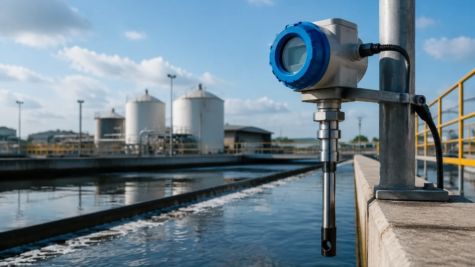
In municipal water treatment, turbidity transmitters monitor the efficiency of coagulation, flocculation, and filtration stages. A spike in turbidity after a sand filter indicates a breakthrough, requiring immediate backwashing. In wastewater, these sensors monitor effluent quality to ensure compliance with environmental discharge permits.
Chemical and Pharmaceutical Processing
Turbidity is used to detect the endpoint of crystallization processes or to monitor the clarity of liquid chemicals. In pharmaceutical manufacturing, it ensures that suspended catalysts have been successfully filtered out of the final product.
Food and Beverage Industry
In dairies and breweries, turbidity transmitters are used for phase separation (e.g., detecting the interface between milk and water or beer and yeast) to reduce product loss during tank changeovers. These sensors must meet hygienic design standards (EHEDG or 3-A).
Integrating Turbidity with Level Measurement Solutions
In complex industrial setups, turbidity data is rarely used in isolation. It is frequently integrated into a broader automation strategy alongside level measurement instruments. For example, in a sedimentation tank, an ultrasonic or radar level sensor may monitor the overall liquid level, while a turbidity transmitter or a sludge blanket level meter determines the clarity of the supernatant or the density of the settled solids.
Professional manufacturers like Welk provide a comprehensive range of industrial level instruments, including radar level meters and ultrasonic sensors, which are often installed in the same vessels as analytical transmitters. For engineers looking to integrate these sensors into comprehensive tank management systems, visiting the Main Page provides access to a full suite of level measurement technologies that complement turbidity data. Combining accurate level data with turbidity readings allows for automated sludge discharge and precise control over tank volumes and chemical dosing.
Frequently Asked Questions
Q: What is the difference between NTU and FNU?
A: NTU (Nephelometric Turbidity Units) is typically used when measuring with a white light source (EPA method), while FNU (Formazin Nephelometric Units) is used when measuring with an infrared light source (ISO 7027). Numerically, they are often equivalent when calibrated with Formazin.
Q: Can a turbidity transmitter measure color?
A: No. Turbidity measures light scattering from particles. While color can interfere with some turbidity measurements (by absorbing light), a standard turbidity transmitter is not designed to quantify the color of a liquid. Specific colorimeters or UV-Vis spectrophotometers are required for color analysis.
Q: How often should I calibrate my turbidity transmitter?
A: This depends on the application. In stable drinking water applications, quarterly calibration may suffice. In high-fouling wastewater environments, monthly calibration and weekly cleaning checks are recommended.
Q: What are the limitations of turbidity measurement?
A: The primary limitations include interference from air bubbles, sensitivity to particle size and shape (two samples with the same mass of solids but different particle sizes will yield different turbidity readings), and the requirement for optical clarity of the sensor windows.
By adhering to these engineering principles and selection guidelines, industrial operators can ensure that their turbidity transmitter provides the reliable data necessary for process optimization and regulatory compliance.