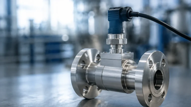
Turbitity Meter
Turbitity Meter
In industrial process control and water quality management, the measurement of liquid clarity is a fundamental parameter for ensuring product consistency and regulatory compliance. A turbitity meter is an analytical instrument designed to quantify the concentration of suspended solids and particulate matter within a liquid medium. While often associated with water treatment, these instruments are critical in chemical processing, food and beverage production, and pharmaceutical manufacturing.
Understanding the technical nuances of a turbitity meter is essential for engineers and plant managers who must integrate these sensors into complex automation systems. This guide provides a technical overview of measurement principles, selection criteria, and installation best practices for industrial turbidity monitoring.
Measurement Principles of Turbidity
Turbidity is not a direct measurement of the weight of suspended solids; rather, it is an optical property that describes how light interacts with particles in a fluid. When a light beam passes through a liquid, suspended particles scatter or absorb the light. The patterns of this scattering depend on the size, shape, and refractive index of the particles, as well as the wavelength of the light source.
Nephelometry (90° Scattering)
The most common method for measuring low to medium levels of turbidity is nephelometry. This technique involves placing a light detector at a 90-degree angle to the incident light beam. When the light hits a particle, it scatters in various directions. The intensity of the light scattered at 90 degrees is proportional to the concentration of particles.
Most international standards, such as ISO 7027 and US EPA 180.1, specify nephelometry for drinking water applications. ISO 7027 typically requires an infrared light source (860 nm) to minimize the interference caused by the color of the liquid, whereas EPA 180.1 specifies a tungsten lamp light source.
Transmission (180° Attenuation)
In applications with high particle concentrations, such as wastewater treatment or industrial slurry monitoring, nephelometry becomes less accurate because the light is scattered multiple times before reaching the detector (multiple scattering). In these cases, a transmission-based turbitity meter is used. The detector is placed directly opposite the light source (180 degrees). The meter measures the decrease in light intensity (attenuation) as it passes through the sample. The more particles present, the less light reaches the detector.
Backscatter (90° to 180°)
For extremely high concentrations of solids, such as sludge density monitoring, backscatter sensors are employed. These sensors detect light reflected back toward the source at an angle greater than 90 degrees. This method is highly effective for thick fluids where light cannot penetrate deeply into the medium.
Technical Selection Criteria
Choosing the correct turbitity meter requires a detailed analysis of the process environment. Engineers must evaluate the expected range of measurement, the chemical compatibility of the sensor housing, and the physical characteristics of the liquid.
| Feature | Nephelometric Sensor | Absorption (Transmission) Sensor | Ratio/Multi-Beam Sensor |
| :— | :— | :— | :— |
| Primary Range | 0–100 NTU | 100–4,000+ NTU | 0–1,000 NTU |
| Sensitivity | Extremely High | Moderate | High |
| Best Use Case | Drinking water, filtered water | Wastewater, raw water, sludge | Process fluids with varying color |
| Color Interference | Low (if using IR) | High | Compensated |
| Standard Compliance | ISO 7027 / EPA 180.1 | Process-specific | Mixed standards |
Light Source Selection
The choice of light source is a critical technical specification:
* Infrared LED (860 nm): Recommended for colored liquids (like pulp or chemical dyes) because the infrared spectrum is less affected by the absorption of visible light by the fluid.
* Tungsten Lamp: Required for compliance with certain regulatory bodies in the United States for drinking water, though they have a shorter lifespan and require more frequent calibration compared to LEDs.
Process Conditions
The temperature and pressure of the process must be confirmed. Standard sensors usually handle up to 50°C (122°F), but high-temperature variants are available for steam condensate or hot chemical processes. Pressure ratings must also match the pipe or vessel specifications, often ranging from 6 bar to 20 bar (87 to 290 psi).
For comprehensive process control, integrating these sensors with high-quality instrumentation found on the Main Page ensures reliable data across the entire facility.
Installation Considerations and Best Practices
The accuracy of a turbitity meter is heavily dependent on how it is installed. Even the most precise sensor will provide erroneous data if it is placed in a location where air bubbles or sediment can interfere with the optical path.
Avoiding Air Bubbles
Air bubbles are the primary enemy of optical turbidity measurement. A bubble scatters light just like a solid particle, leading to falsely high readings.
* De-bubblers: In bypass installations, a de-bubbling chamber should be installed before the sensor to allow air to escape.
* Pressure Maintenance: Keeping the sample under slight pressure can help keep gases in solution.
* Orientation: In-line sensors should be installed on vertical pipes with an upward flow direction to ensure the pipe remains full and bubbles are swept away.
Flow Rate and Turbulence
While a certain amount of flow is necessary to keep the sensor face clean and ensure a representative sample, excessive turbulence can create micro-bubbles. Conversely, if the flow is too slow, particles may settle out of the liquid, leading to falsely low readings. A flow rate between 0.5 and 2.0 liters per minute is typically ideal for bypass systems.
Stray Light and Wall Effects
In open-tank or large-pipe installations, "stray light" from external sources or reflections from the pipe walls can reach the detector. Using sensors with integrated light shields or installing the sensor in a dark, non-reflective chamber is essential for maintaining a low detection limit.
Maintenance and Calibration
Industrial turbitity meters are sensitive optical instruments that require regular maintenance to prevent "sensor fouling." Biofilm growth, mineral scaling, or oil coatings on the optical windows will degrade performance.
Cleaning Cycles
Many modern sensors feature integrated cleaning systems, such as:
* Mechanical Wipers: A rubber or silicone blade that periodically wipes the glass window.
* Ultrasonic Cleaning: High-frequency vibrations that prevent particles from adhering to the sensor face.
* Air/Water Jets: Periodic bursts of compressed air or clean water to flush the sensor area.
Calibration Standards
Calibration should be performed using primary standards, most commonly Formazin. Formazin is a synthetic polymer that produces a consistent and repeatable light-scattering pattern. Because Formazin is toxic and has a limited shelf life, many facilities use secondary standards (such as stabilized Formazin or gel-based standards) for routine verification, while reserving primary Formazin for annual or semi-annual calibrations.

Common Risks and Limitations
Engineers must be aware of the inherent limitations of optical turbidity measurement to avoid data misinterpretation.
1. Particle Size Sensitivity: A turbitity meter is more sensitive to small particles than large ones for a given mass concentration. If the particle size distribution in the process changes significantly, the turbidity reading may change even if the total suspended solids (TSS) remain constant.
2. Color Interference: Even with infrared light sources, extremely dark or opaque fluids can absorb so much light that the detector cannot function. In these cases, the path length of the sensor must be shortened.
3. Fouling: In chemical applications, certain substances can etch the glass or plastic windows of the sensor, leading to permanent damage and the need for frequent replacement.
Frequently Asked Questions (FAQ)
Q: What is the difference between NTU and FNU?
A: NTU (Nephelometric Turbidity Units) is typically used when the measurement is performed with a white light source (tungsten lamp) according to EPA 180.1. FNU (Formazin Nephelometric Units) is used when the measurement is performed with an infrared light source (860 nm) according to ISO 7027. Numerically, they are often similar but not always interchangeable in regulated applications.
Q: Can a turbitity meter measure Total Suspended Solids (TSS)?
A: Yes, but only through correlation. You must take laboratory samples of the liquid at various turbidity levels to create a mathematical curve that relates NTU to mg/L of solids. This correlation is only valid as long as the particle type and size remain consistent.
Q: How often should I calibrate my sensor?
A: For drinking water applications, regulatory bodies often require monthly verification. In industrial process applications, a quarterly calibration is usually sufficient, provided the sensor has an automatic cleaning mechanism.
Q: Does pipe material affect the measurement?
A: For in-line sensors, the internal reflection of the pipe can matter. Stainless steel pipes are highly reflective and may require the sensor to be installed in a specialized flow cell or black-lined pipe section to prevent stray light interference.
Conclusion and Project Confirmation
Implementing a turbitity meter system requires more than just purchasing a sensor; it requires a holistic view of the fluid dynamics and chemical properties of the process. Before finalizing a project specification, technical teams should confirm the following:
* The specific regulatory standard required (ISO vs. EPA).
* The range of expected turbidity, including potential spikes during process upsets.
* The presence of chemical agents that could damage optical seals or windows.
* The availability of clean water or air for automated cleaning systems.
By addressing these factors during the design phase, industrial operators can ensure long-term accuracy and minimize the total cost of ownership for their analytical instrumentation.