Ultrasonic Clamp on Flow Meters
Ultrasonic Clamp on Flow Meters
In the landscape of industrial process control, the ability to measure fluid flow without interrupting operations is a significant advantage. Ultrasonic clamp on flow meters have emerged as a primary solution for facilities seeking to monitor liquid movement without the need for pipe cutting, welding, or process downtime. As a non-invasive technology, these instruments provide high accuracy and reliability across a diverse range of industries, from water treatment to chemical processing and oil and gas production.
This guide provides a comprehensive technical overview of ultrasonic clamp on flow meters, detailing their operating principles, selection criteria, and installation requirements to assist engineers in making informed procurement and implementation decisions.
Measurement Principles and Technology
Ultrasonic flow measurement relies on the propagation of sound waves through a moving fluid. Unlike mechanical meters that use moving parts (such as turbines or paddewheels), ultrasonic meters use electronic transducers to send and receive acoustic signals. There are two primary methods used in ultrasonic clamp on flow meters: Transit-Time and Doppler Effect.
Transit-Time Method
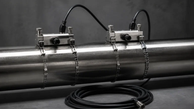
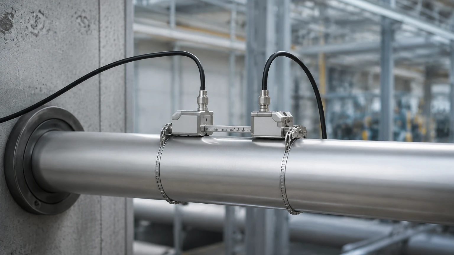
Transit-time technology is the most common method for measuring clean liquids. It operates on the principle of time difference. Two transducers are mounted on the exterior of the pipe, acting as both transmitters and receivers. One transducer sends a signal upstream, and the other sends a signal downstream.
Sound waves traveling with the flow move faster than those traveling against it. The meter measures the time difference between these two signals (typically in nanoseconds). This time difference is directly proportional to the velocity of the fluid. By incorporating the pipe’s cross-sectional area, the device calculates the volumetric flow rate. This method is highly accurate for liquids with low concentrations of suspended solids or entrained air (typically less than 2% by volume).
Doppler Effect Method
The Doppler method is utilized for liquids containing significant amounts of suspended solids or gas bubbles. The transducers transmit a continuous high-frequency sound wave into the fluid. This sound reflects off particles or bubbles (discontinuities) moving with the flow. Due to the Doppler effect, the frequency of the reflected signal is shifted relative to the transmitted signal. The frequency shift is proportional to the velocity of the reflecting particles. While generally less precise than transit-time meters, Doppler meters are essential for slurries, wastewater, and aerated liquids where transit-time signals would be absorbed or scattered.
Key Advantages of Non-Invasive Measurement
Implementing ultrasonic clamp on flow meters offers several strategic benefits for industrial automation:
1. Zero Process Interruption: Since transducers are clamped to the outside of the pipe, there is no need to depressurize the system or cut into the piping. This is critical for 24/7 operations.
2. No Pressure Drop: Because there are no internal components obstructing the flow path, there is no permanent pressure loss, which improves energy efficiency in pumping systems.
3. Chemical Compatibility: The sensors never come into contact with the process fluid. This makes them ideal for corrosive, toxic, or high-purity liquids (such as deionized water or aggressive acids) where sensor degradation or contamination would be a concern.
4. Versatility: A single portable meter can be used to verify flow across various pipe sizes and materials throughout a facility.
5. Leak-Free Design: Eliminating pipe penetrations removes potential leak points, enhancing site safety and environmental compliance.
Selection Criteria for Industrial Applications
Choosing the correct ultrasonic clamp on flow meters requires a detailed understanding of the application environment. Engineers should evaluate the following parameters:
Pipe Specifications
* Material: Most meters work well with carbon steel, stainless steel, cast iron, PVC, and HDPE. However, materials like concrete or heavily lined pipes (e.g., thick rubber or cement lining) can attenuate the ultrasonic signal.
* Diameter: Meters are available for a wide range of sizes, typically from DN15 (1/2") up to DN6000 (240").
* Wall Thickness: Accurate measurement of the pipe wall thickness is mandatory, as it influences the calculation of the sound path.
Fluid Characteristics
* Velocity Range: Ensure the meter can handle the expected flow range, typically from 0.01 m/s to 12 m/s.
* Temperature: Standard transducers usually handle up to 80°C, while specialized high-temperature versions can withstand up to 250°C.
* Fluid Type: Confirm whether the liquid is "acoustically conductive." Clean water, oils, and chemicals are generally excellent candidates.
Accuracy and Output
* Precision: High-end transit-time meters offer accuracy within ±0.5% to ±1.0% of the flow rate.
* Integration: Consider the required output signals, such as 4-20mA, RS485 (Modbus), or pulse outputs for totalizing.
Practical Selection Table
The following table provides a general comparison for selecting between different configurations of ultrasonic clamp on flow meters.
| Feature | Portable/Handheld | Wall-Mounted (Fixed) | Explosion-Proof (Ex) |
| :— | :— | :— | :— |
| Primary Use | Auditing, Spot-checks | Permanent Monitoring | Hazardous Areas (Oil/Gas) |
| Power Source | Internal Battery | AC/DC Hardwired | AC/DC Hardwired |
| Data Logging | High capacity (SD Card) | Optional | Standard |
| Pipe Size Range | DN15 – DN6000 | DN15 – DN6000 | DN50 – DN3000 |
| Protection Class | IP65/IP67 | IP65/IP66 | IP68 / Ex d II B T4 |
| Installation | Temporary (Straps) | Permanent (Clamps/Rails) | Permanent (Bolted Rails) |
Installation Guidelines for Optimal Accuracy
To ensure the reliability of ultrasonic clamp on flow meters, proper installation is paramount. The most common cause of measurement error is poor transducer placement.
Straight Pipe Run Requirements
Ultrasonic meters require a fully developed flow profile. As a general rule of thumb, installers should provide:
* Upstream: 10 pipe diameters (10D) of straight pipe after any elbows, valves, or pumps.
* Downstream: 5 pipe diameters (5D) of straight pipe before any subsequent fittings.
If the fluid is highly turbulent (e.g., immediately after a dual-plane elbow), the upstream requirement may increase to 20D or 40D.
Mounting Configurations
There are three primary ways to mount transducers, depending on pipe size and fluid conditions:
1. V-Method: The signals bounce once off the opposite pipe wall. This is the standard for pipes between DN25 and DN200.
2. Z-Method: Transducers are mounted on opposite sides of the pipe. The signal crosses the pipe once. This is used for large pipes (above DN200) or where the fluid is slightly attenuating.
3. W-Method: The signal bounces three times. This is used for very small pipes (DN15 to DN50) to increase the transit time and improve resolution.
Coupling and Surface Preparation
Because air is a poor conductor of ultrasound, a coupling agent (ultrasonic grease or gel) must be applied between the transducer face and the pipe surface. The pipe surface should be cleaned of rust, loose paint, or scale to ensure a solid acoustic bond.
Operational Limitations and Common Risks
While highly versatile, ultrasonic clamp on flow meters are not universal solutions. Engineers must be aware of the following limitations:
* Signal Attenuation: Materials like fiberglass, concrete, or pipes with internal air gaps (such as some plastic-lined pipes) can prevent the signal from reaching the fluid.
* Aeration and Cavitation: Excessive bubbles caused by pumps or valves will scatter the ultrasonic beam, leading to a "signal loss" error.
* Pipe Scaling: Internal buildup (limescale or paraffin) changes the internal diameter and the sound velocity, leading to inaccurate readings if not accounted for in the meter settings.
* Zero-Flow Drift: In very low-flow applications, thermal gradients in the pipe can cause the meter to report a small flow when none exists. Regular zero-point calibration is recommended.
Maintenance and Troubleshooting FAQ
Q: How often should the coupling gel be replaced?
A: For permanent installations, high-quality silicone-based coupling grease can last several years. However, in outdoor or high-temperature environments, it is good practice to inspect the signal strength annually and re-apply gel if the signal has degraded.
Q: Can these meters measure steam or gas?
A: Standard clamp-on meters discussed here are designed for liquids. While specialized ultrasonic gas flow meters exist, they operate at different frequencies and often require different hardware configurations.
Q: What happens if the pipe is not full?
A: Ultrasonic flow meters require a full pipe to function correctly. If the pipe is partially full, the sound path will be interrupted by the air pocket, and the meter will fail to provide a reading.
Conclusion and System Integration
Ultrasonic clamp on flow meters represent a sophisticated, cost-effective, and low-maintenance approach to industrial flow monitoring. By understanding the physics of transit-time and Doppler measurement, and by adhering to strict installation protocols regarding pipe runs and coupling, facilities can achieve high-precision data without the risks associated with traditional inline meters.
For organizations managing complex fluid systems, integrating flow data with level measurement is essential for comprehensive mass balance and inventory control. Welk provides a wide array of industrial measurement solutions, including radar and ultrasonic level sensors, designed to work in tandem with flow instrumentation for complete process transparency. To explore specific product options and receive application support for your next project, visit our Main Page.
By selecting the right technology and following engineering best practices, operators can ensure long-term accuracy and operational efficiency in their flow measurement applications.