Differential Pressure Flow Transmitter
Differential Pressure Flow Transmitter
Differential pressure (DP) flow measurement remains one of the most prevalent methods for quantifying fluid movement in industrial processes. A differential pressure flow transmitter works in conjunction with a primary flow element to convert the kinetic energy of a moving fluid into a measurable pressure difference. This technology is valued for its versatility across liquid, gas, and steam applications, as well as its adherence to long-established international standards such as ISO 5167.
Understanding the engineering principles behind these devices is essential for selecting the correct configuration for specific industrial environments. This guide explores the measurement physics, hardware components, selection criteria, and installation best practices for the differential pressure flow transmitter.
Measurement Principles
The operation of a differential pressure flow transmitter is based on Bernoulli’s principle, which states that as the speed of a moving fluid increases, the pressure within the fluid decreases. In a piping system, this is achieved by introducing a physical restriction—known as a primary element—into the flow stream.
The Bernoulli Equation and Flow Velocity
When a fluid passes through a restriction, its velocity increases to maintain the continuity of mass flow. According to the law of conservation of energy, this increase in kinetic energy must be balanced by a decrease in static pressure. The relationship is mathematically expressed as:
$$Q = k \cdot \sqrt{\Delta P}$$
Where:
* Q is the flow rate.
* k is a constant derived from the pipe diameter, fluid density, and the geometry of the restriction.
* ΔP (Differential Pressure) is the difference between the upstream pressure ($P_1$) and the downstream pressure ($P_2$).
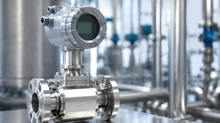
Because the flow rate is proportional to the square root of the differential pressure, the transmitter must often perform a "square root extraction" to provide a linear output signal (such as 4-20mA) that represents the actual flow rate. Modern digital transmitters, such as those featured on the Main Page of industrial instrumentation catalogs, typically handle this calculation internally.
Primary Elements: The Source of Differential Pressure
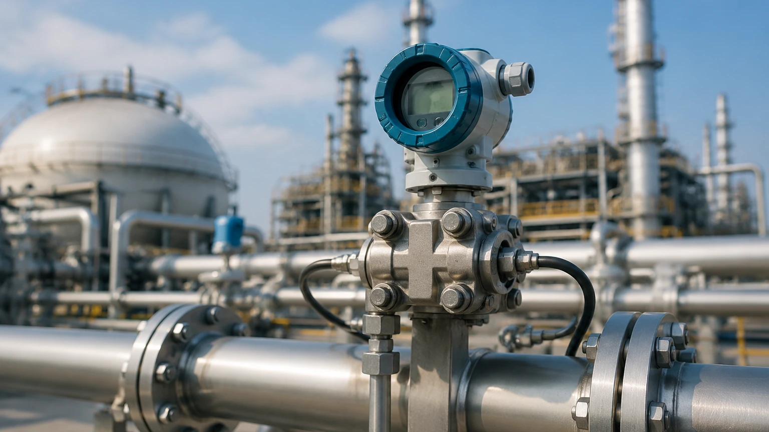
The differential pressure flow transmitter itself is the "secondary element." It requires a "primary element" to create the pressure drop. The choice of primary element significantly impacts accuracy, permanent pressure loss, and maintenance requirements.
Orifice Plates
The orifice plate is a thin metal disk with a precision-machined hole (bore) in the center. It is the most common primary element due to its low cost and ease of installation between standard flanges. However, it creates a significant permanent pressure loss (PPL) and is susceptible to wear over time, especially with abrasive fluids.
Venturi Tubes
A Venturi tube consists of a converging conical section, a cylindrical throat, and a diverging recovery section. This design is highly efficient, offering the lowest permanent pressure loss of all DP elements. It is ideal for high-velocity flows and applications where energy conservation is critical, though it is more expensive and physically larger than an orifice plate.
Flow Nozzles
Flow nozzles are often used for high-temperature and high-velocity steam applications. They are more rugged than orifice plates and offer better pressure recovery, making them a middle-ground solution between the orifice plate and the Venturi tube.
Pitot Tubes and Averaging Pitot Tubes
Unlike the previous elements that restrict the entire flow stream, a Pitot tube measures the point velocity by comparing impact pressure to static pressure. Averaging Pitot tubes (often called Annubars) use multiple sensing ports across the pipe diameter to provide a more representative flow profile. These are excellent for large diameter pipes where installing a full-bore restriction would be cost-prohibitive.
Selection Criteria for Differential Pressure Flow Transmitters
Selecting the right differential pressure flow transmitter requires a detailed analysis of the process conditions. Engineers must balance accuracy requirements against budget and installation constraints.
Fluid Properties
* State: Is the fluid a liquid, gas, or saturated/superheated steam?
* Viscosity: High-viscosity fluids may require specialized primary elements like wedge meters to prevent clogging and ensure a stable Reynolds number.
* Corrosivity: The wetted parts of the transmitter (diaphragms and manifolds) must be compatible with the process media. Common materials include 316L Stainless Steel, Hastelloy C, or Tantalum.
Turndown Ratio
The turndown ratio is the range over which a transmitter can measure accurately. Because of the square root relationship, a standard differential pressure flow transmitter typically has a limited turndown (often 4:1 or 5:1) compared to magnetic or ultrasonic meters. If the process requires measuring very low and very high flows with the same device, high-performance transmitters with advanced sensing cells are required.
Accuracy and Repeatability
In custody transfer applications, high accuracy (±0.05% of span) is required. For general process monitoring, a standard accuracy of ±0.2% to ±0.5% may suffice. It is important to distinguish between "reference accuracy" and "installed accuracy," the latter of which accounts for temperature and static pressure effects.
Technical Comparison of Primary Elements
| Feature | Orifice Plate | Venturi Tube | Flow Nozzle | Averaging Pitot Tube |
| :— | :— | :— | :— | :— |
| Initial Cost | Low | High | Medium | Low/Medium |
| Pressure Loss | High | Very Low | Medium | Very Low |
| Accuracy | Good (1-2%) | Excellent (0.5-1%) | Good (1-1.5%) | Fair (1-3%) |
| Suitability | Clean liquids/gases | Slurries/High flow | Steam/High temp | Large pipes |
| Installation | Easy (between flanges) | Difficult (long body) | Moderate | Easy (insertion) |
Installation Considerations
The performance of a differential pressure flow transmitter is heavily dependent on how it is installed. Improper piping or orientation can lead to significant measurement errors.
Straight Pipe Requirements
To ensure a fully developed flow profile, primary elements require a specific length of straight pipe upstream and downstream. Typically, 10 to 20 diameters (D) upstream and 5D downstream are required. If the installation site has multiple elbows or valves close to the meter, flow conditioners may be necessary to eliminate swirl.
Impulse Line Routing
Impulse lines (the small-bore tubes connecting the pipe taps to the transmitter) must be carefully managed:
* Gas Service: The transmitter should be mounted above the pipe so that any condensed liquid drains back into the process line.
* Liquid/Steam Service: The transmitter should be mounted below the pipe to ensure the impulse lines remain full of liquid and to allow gas bubbles to vent back into the pipe.
* Sloping: Impulse lines should always be sloped (at least 1:12) to prevent trapped gas or liquid pockets.
Manifold Usage
A 3-way or 5-way valve manifold is essential for every differential pressure flow transmitter installation. These manifolds allow the operator to isolate the transmitter from the process, equalize the pressure for zero-point calibration, and bleed the lines without shutting down the entire process.
Limitations and Risks
While DP flow measurement is reliable, it is not without its drawbacks. Engineers should be aware of the following risks:
1. Permanent Pressure Loss (PPL): Every restriction causes a loss of energy. In high-volume pumping systems, the electricity cost to overcome the PPL of an orifice plate can exceed the cost of the meter itself within a few years.
2. Impulse Line Plugging: In dirty or viscous services, the small impulse lines can become blocked by solids or frozen in cold climates. This requires regular purging or the use of chemical seals (diaphragm seals).
3. Square Root Sensitivity: At the lower end of the flow scale (below 25% of maximum flow), the differential pressure signal becomes very small. Small errors in pressure sensing are magnified when the square root is taken, leading to poor accuracy at low flow rates.
4. Density Changes: DP meters measure mass flow indirectly. If the fluid density changes due to temperature or pressure fluctuations, the volumetric flow calculation will be incorrect unless a multivariable transmitter (measuring P, ΔP, and T) is used.
Maintenance and Calibration
Routine maintenance ensures the longevity of the measurement loop. For the primary element, this involves periodic inspection for edge sharpness (in orifice plates) or buildup. For the differential pressure flow transmitter, electronic calibration should be performed annually.
Zero-Trim Procedure:
One of the most common maintenance tasks is the zero-trim. Over time, the transmitter may show a small non-zero reading even when there is no flow. By using the manifold to equalize the high and low-pressure sides, the technician can reset the "zero" point to account for mounting position or static pressure effects.
Frequently Asked Questions (FAQ)
Q: Can a differential pressure flow transmitter measure flow in both directions?
A: Standard orifice-based systems are unidirectional. However, using a symmetrical primary element and a bi-directional transmitter allows for flow measurement in both directions, though accuracy may vary slightly.
Q: What is the difference between a DP transmitter and a Multivariable transmitter?
A: A standard DP transmitter only measures the pressure difference. A multivariable transmitter measures differential pressure, static pressure, and process temperature simultaneously, allowing it to calculate compensated mass flow in real-time.
Q: How do I handle steam flow measurement to prevent damaging the transmitter?
A: Siphons or condensation pots must be used in steam service. These components trap a volume of condensed water in the impulse lines, acting as a thermal barrier that protects the transmitter's sensitive diaphragms from high steam temperatures.
Q: Why is my flow reading fluctuating wildly?
A: This is often caused by "noise" in the flow stream, such as turbulence from a nearby pump or valve. Most transmitters offer a "damping" setting (measured in seconds) that smooths the output signal by averaging the readings over a set period.
Conclusion
The differential pressure flow transmitter remains a fundamental tool in industrial automation. By understanding the relationship between fluid velocity and pressure drop, and by carefully selecting the appropriate primary element and installation configuration, engineers can achieve reliable and cost-effective flow monitoring. For those seeking specific hardware specifications or customized measurement solutions, visiting the Main Page provides access to a wide range of industrial instrumentation designed for the rigors of modern process control.