Ultrasonic Flow Rate Sensor
Ultrasonic Flow Rate Sensor
In the landscape of industrial process control, the ability to measure fluid movement without interrupting the flow or compromising the integrity of the piping system is a significant advantage. The ultrasonic flow rate sensor has emerged as a primary solution for these requirements, offering a non-invasive, highly accurate, and low-maintenance method for monitoring liquids across various industries. As a specialized manufacturer of industrial measurement instruments, Welk provides this guide to help engineers and procurement professionals understand the technical foundations and application nuances of ultrasonic flow technology.
Fundamental Measurement Principles
Ultrasonic flow measurement relies on the propagation of high-frequency sound waves through a moving fluid. Unlike mechanical meters that use moving parts like turbines or paddles, an ultrasonic flow rate sensor uses electronic transducers to send and receive acoustic signals. There are two primary methods used in industrial applications: Transit-Time and Doppler Effect.
Transit-Time Method
The transit-time principle is the most common for clean liquids. It operates on the fact that sound waves traveling in the direction of the flow move faster than those traveling against the flow. Two transducers are placed on the pipe, acting as both transmitters and receivers. They send ultrasonic pulses back and forth.
If $t_{up}$ is the time taken for the signal to travel upstream and $t_{down}$ is the time taken to travel downstream, the difference in time ($Δt$) is directly proportional to the velocity of the liquid. The sensor calculates the flow rate by integrating this velocity with the known cross-sectional area of the pipe. This method requires the fluid to be relatively free of suspended solids or entrained air, as these can scatter the signal.
Doppler Effect Method
The Doppler effect method is utilized for liquids containing particles, bubbles, or high turbidity. It works by transmitting an ultrasonic signal of a known frequency into the fluid. This signal reflects off moving discontinuities (solids or bubbles). Because the reflectors are moving, the frequency of the reflected signal is shifted. This frequency shift (the Doppler shift) is measured by the sensor and is proportional to the flow velocity. While transit-time sensors require "clean" water, Doppler sensors require "dirty" water to function correctly.
Technical Selection Criteria
Selecting the correct ultrasonic flow rate sensor requires a detailed analysis of the process environment. Engineers must evaluate several factors to ensure long-term reliability and accuracy.
Fluid Properties
The chemical composition, temperature, and viscosity of the fluid are paramount. For transit-time sensors, the fluid must be sonically conductive. High-viscosity fluids can affect the flow profile, moving it from turbulent to laminar, which requires the sensor's internal software to apply correction factors. Temperature also affects the speed of sound in the medium; therefore, high-quality sensors often include temperature compensation algorithms.
Pipe Material and Condition
Ultrasonic waves must pass through the pipe wall. Materials such as carbon steel, stainless steel, PVC, and ductile iron are generally excellent conductors. However, pipes with internal liners (like cement or thick rubber) or significant scale buildup can attenuate the signal. It is essential to confirm the pipe material and wall thickness before selecting a transducer frequency.
Accuracy and Rangeability
Most industrial-grade ultrasonic sensors offer an accuracy of ±1% to ±2% of the flow rate. They also boast a high turndown ratio (often 100:1 or higher), meaning they can measure very low velocities (e.g., 0.1 m/s) and very high velocities (up to 12 m/s or 40 ft/s) with consistent performance. For applications requiring the highest precision, such as custody transfer, inline ultrasonic meters are preferred over clamp-on versions.
Selection Table: Transit-Time vs. Doppler
| Feature | Transit-Time Sensor | Doppler Effect Sensor |
| :— | :— | :— |
| Fluid Type | Clean liquids, water, chemicals | Slurries, wastewater, aerated liquids |
| Suspended Solids | < 2% by volume | > 100 ppm (minimum size 75-100 microns) |
| Typical Accuracy | ±0.5% to ±2% | ±2% to ±5% |
| Installation | Inline or Clamp-on | Usually Clamp-on |
| Pipe Size Range | 10 mm to 6000 mm | 25 mm to 6000 mm |
| Primary Use Case | Potable water, HVAC, oil/gas | Mining, sewage, chemical waste |
Installation Guidelines and Best Practices
The performance of an ultrasonic flow rate sensor is heavily dependent on its installation. Unlike level measurement devices found on our Main Page, which are often top-mounted, flow sensors are sensitive to the hydraulic profile within the pipe.
Straight Pipe Requirements
To ensure a stable, fully developed flow profile, sensors should be installed in a straight section of pipe. The general rule of thumb is the "10D and 5D" rule: the sensor requires 10 diameters of straight pipe upstream and 5 diameters downstream from any disturbance (elbows, valves, or pumps). If space is limited, flow conditioners may be necessary.
Transducer Mounting Methods
For clamp-on sensors, there are three common mounting configurations:
1. V-Method: The signals bounce off the opposite pipe wall once. This is the standard for pipes ranging from 25 mm to 400 mm (1 to 16 inches).
2. Z-Method: Transducers are mounted on opposite sides of the pipe. This is used for large pipes or where the signal attenuation is high.
3. W-Method: The signal bounces three times. This is typically used for very small pipes (under 50 mm) to increase the transit time and improve resolution.
Coupling and Signal Integrity
In clamp-on applications, an acoustic coupling agent (grease or gel) must be applied between the transducer face and the pipe surface to eliminate air gaps. For permanent installations, solid epoxy or silicone couplants are used to prevent the gel from drying out over time.
Limitations and Operational Challenges
While highly versatile, ultrasonic technology is not a universal solution. Understanding its limitations prevents costly misapplications.
* Entrained Air: In transit-time systems, even a small percentage of air bubbles can block the ultrasonic signal entirely, leading to a "Signal Lost" error.
* Pipe Wall Attenuation: Extremely thick-walled pipes or pipes made of composite materials with air pockets can prevent the signal from reaching the fluid.
* Reynolds Number Sensitivity: Ultrasonic meters are sensitive to the flow profile. If the Reynolds number is in the transitional zone between laminar and turbulent flow, accuracy may decrease unless the meter's processor can compensate.
* Temperature Extremes: Standard transducers are usually rated up to 120°C (248°F). For high-temperature steam or thermal oil applications, specialized high-temperature transducers and mounting rails are required.
Maintenance and Troubleshooting
One of the primary benefits of an ultrasonic flow rate sensor is the lack of maintenance required for the sensor itself, as there are no bearings to wear or rotors to clog. However, the installation environment requires periodic checks.
1. Couplant Inspection: For clamp-on sensors, check the coupling agent every 12 to 24 months. If the signal strength (often measured in decibels or as a percentage) has dropped, the couplant may need to be reapplied.
2. Signal-to-Noise Ratio (SNR): Modern digital signal processing (DSP) allows users to monitor the SNR. A decreasing SNR often indicates pipe scaling or external electrical interference.
3. Zero-Flow Calibration: Periodically, it is advisable to perform a zero-flow check. This involves stopping the flow completely (ensuring the pipe remains full) and verifying that the sensor reads zero. This compensates for any electronic drift.
Integration with Level Measurement Systems
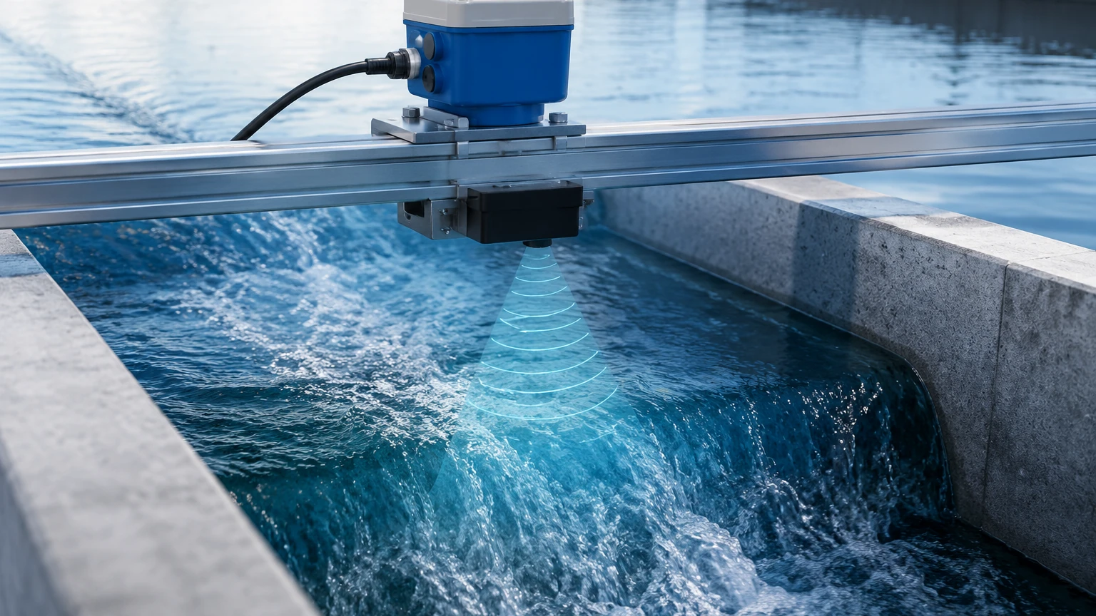
In many industrial applications, flow measurement is only one part of the equation. For example, in open channel flow (like flumes or weirs), an ultrasonic level sensor is used to measure the head of the water, which is then converted into a flow rate using standard hydraulic formulas.
For engineers designing comprehensive fluid management systems, coordinating flow data with level data is essential. Whether you are monitoring a chemical storage tank or a municipal water reservoir, integrating high-quality instruments ensures process safety. You can explore our range of level measurement technologies, including radar and hydrostatic transmitters, on our Main Page.
Frequently Asked Questions (FAQ)
Q: Can ultrasonic flow sensors measure gas flow?
A: Yes, but gas flow requires specialized high-power transducers because gases are much less dense than liquids and attenuate ultrasonic signals significantly. Most standard industrial sensors are designed for liquids.
Q: Does the pipe need to be full?
A: Yes, for standard transit-time and Doppler sensors, the pipe must be completely full. If the pipe is partially full, the sound waves will reflect off the air-liquid interface, resulting in inaccurate or no readings. For partially full pipes, an area-velocity sensor (combining level and velocity) is required.
Q: How do I know if my pipe has too much scale for a clamp-on sensor?
A: Most modern sensors provide a diagnostic value for "Signal Strength." If the signal strength is low despite proper mounting and couplant, it is likely that internal scale or a liner is attenuating the signal. In such cases, an inline ultrasonic meter or an electromagnetic meter may be necessary.
Q: Is the sensor affected by fluid conductivity?
A: No. Unlike electromagnetic flow meters, ultrasonic sensors are independent of the fluid's electrical conductivity. This makes them ideal for deionized water, hydrocarbons, and non-conductive chemicals.
Conclusion
The ultrasonic flow rate sensor represents a pinnacle of non-intrusive measurement technology. By understanding the distinction between transit-time and Doppler principles, adhering to strict installation geometry, and considering the specific acoustic properties of the pipe and fluid, industrial operators can achieve precise flow monitoring with minimal operational downtime. For further technical specifications and to view our full catalog of level and flow solutions, please visit our Main Page.