Ultrasonic Flow Sensor
Ultrasonic Flow Sensor
Ultrasonic flow sensors represent a sophisticated category of non-intrusive measurement technology designed to determine the velocity of a fluid within a closed conduit. By utilizing high-frequency sound waves, these instruments provide accurate data without the need for moving parts or physical contact with the process media. In the context of industrial automation, particularly within sectors like water treatment, chemical processing, and oil and gas, ultrasonic flow sensors have become indispensable tools for monitoring efficiency and ensuring process safety.
As a professional manufacturer of industrial measurement instruments, Welk provides these solutions to complement a broader suite of level measurement technologies. Understanding the underlying physics and application constraints of these sensors is essential for engineers and plant managers who require reliable, cost-effective measurement solutions. For those exploring a full range of industrial instrumentation, including radar and ultrasonic level sensors, visiting the Main Page offers a comprehensive look at available technology and application support.
Measurement Principles of Ultrasonic Flow Sensors
Ultrasonic flow measurement is primarily based on two distinct physical principles: Transit-Time and the Doppler Effect. The choice between these two methods depends entirely on the characteristics of the fluid being measured.
Transit-Time Method
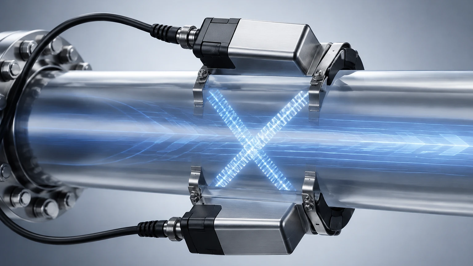
The transit-time principle is the most common method for measuring clean liquids. This technique utilizes two transducers, located on opposite sides of a pipe or at a specific distance from each other along the pipe wall. These transducers act as both transmitters and receivers.
1. Upstream and Downstream Transmission: The sensor sends an ultrasonic pulse from the upstream transducer to the downstream transducer, and then reverses the direction.
2. Time Difference: Sound traveling with the flow (downstream) moves faster than sound traveling against the flow (upstream).
3. Calculation: The difference in transit time is directly proportional to the velocity of the liquid. By knowing the pipe's cross-sectional area, the meter calculates the volumetric flow rate.
Transit-time sensors are highly accurate for fluids with low turbidity, such as potable water, deionized water, and clear chemicals.
Doppler Effect Method
The Doppler effect method is utilized for fluids that contain suspended solids or entrained gas bubbles. These particles act as reflectors for the ultrasonic signal.
1. Frequency Shift: A transducer transmits a continuous ultrasonic signal of a known frequency into the liquid.
2. Reflection: The signal reflects off the moving particles or bubbles within the fluid.
3. Measurement: Because the reflectors are moving, the frequency of the reflected signal is shifted (the Doppler shift). The magnitude of this shift is proportional to the velocity of the reflectors, and by extension, the fluid itself.
Doppler sensors are ideal for wastewater, slurries, and aerated liquids where transit-time signals would otherwise be blocked or scattered.
Key Components and Design Configurations
An ultrasonic flow sensor system typically consists of two main components: the transducers (the "wet" or "dry" interface) and the electronic signal converter.
Transducers
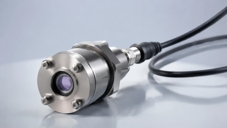
Transducers contain piezoelectric crystals that convert electrical energy into mechanical vibrations (ultrasonic pulses) and vice versa. There are two primary mounting configurations:
* Clamp-on Sensors: These are mounted on the exterior of the pipe. They are highly valued for their ease of installation, as they do not require pipe cutting or process downtime. They are also immune to pressure and chemical compatibility issues since they never touch the fluid.
* Inline (Wetted) Sensors: These are integrated into a pipe section or spool piece. The transducers are in direct contact with the fluid. While they require more intensive installation, they often provide higher accuracy and are less affected by pipe wall conditions.
Signal Converter
The converter processes the raw signals from the transducers. Modern converters use advanced digital signal processing (DSP) to filter out noise, compensate for temperature changes, and provide various outputs such as 4-20mA, pulse, or digital protocols like Modbus and HART.
Selection Criteria for Industrial Applications
Choosing the correct ultrasonic flow sensor requires a detailed analysis of the application environment. Selecting the wrong technology can lead to signal loss or significant measurement errors.
Fluid Characteristics
The first step is determining if the fluid is "clean" or "dirty." Transit-time sensors require less than 2% total suspended solids (TSS) or aeration. If the TSS exceeds this or if there is significant entrainment, a Doppler sensor is required.
Pipe Material and Condition
For clamp-on sensors, the ultrasonic signal must pass through the pipe wall. Materials like carbon steel, stainless steel, and most plastics are excellent conductors of sound. However, pipes with internal liners (like cement or thick rubber) or those with significant internal scaling/corrosion can attenuate the signal, making measurement difficult or impossible.
Flow Profile and Reynolds Number
Ultrasonic meters are sensitive to the flow profile. They perform best in fully developed laminar or turbulent flow. The Reynolds number, a dimensionless value representing the ratio of inertial forces to viscous forces, helps determine the flow regime. Most ultrasonic meters include software to compensate for changes in the flow profile based on the Reynolds number.
Selection Table: Transit-Time vs. Doppler
| Feature | Transit-Time | Doppler |
| :— | :— | :— |
| Ideal Fluid | Clean liquids (Water, Oil, Chemicals) | Dirty liquids (Slurries, Sewage, Aerated fluids) |
| Solids/Bubbles | < 2% by volume | > 100 ppm (typically > 0.5% – 2%) |
| Accuracy | 0.5% to 1.0% of flow rate | 2.0% to 5.0% of full scale |
| Pipe Sizes | 12.7 mm to 5000 mm (0.5" to 200") | 25 mm to 2500 mm (1" to 100") |
| Installation | Clamp-on or Inline | Usually Clamp-on |
Installation Considerations and Best Practices
Proper installation is the single most important factor in the performance of an ultrasonic flow sensor. Even the most advanced sensor will fail if the physical setup is flawed.
Straight Pipe Requirements
To ensure a stable and predictable flow profile, the sensor must be installed in a straight section of pipe.
* Upstream: Typically requires 10 to 20 pipe diameters (10D – 20D) of straight pipe after any elbows, valves, or pumps.
* Downstream: Typically requires 5 pipe diameters (5D) of straight pipe before any subsequent obstructions.
If these distances cannot be met, flow conditioners may be necessary, or the user must accept a decrease in specified accuracy.
Mounting Position
On horizontal pipes, transducers should be mounted at the "3 o'clock" and "9 o'clock" positions (the sides of the pipe). Avoid the top (12 o'clock) where air bubbles may collect, and the bottom (6 o'clock) where sediment may settle, as both conditions will interfere with the ultrasonic signal.
For vertical pipes, the flow should always be in an upward direction to ensure the pipe remains completely full. A partially full pipe is a common cause of measurement failure in ultrasonic systems.
Coupling Agents
For clamp-on installations, a coupling agent (acoustic gel or grease) is applied between the transducer face and the pipe wall. This eliminates air gaps that would otherwise reflect the ultrasonic energy before it enters the pipe. In permanent installations, solid coupling pads or high-temperature silicone may be used to ensure long-term signal integrity.
Limitations and Common Challenges
While highly versatile, ultrasonic flow sensors have specific limitations that must be managed:
1. Signal Attenuation: Extremely viscous liquids or highly aerated fluids can absorb the ultrasonic energy, leading to a "Signal Lost" error.
2. Temperature Extremes: Standard transducers are often rated up to 120°C (248°F). High-temperature applications require specialized transducers and mounting hardware to protect the piezoelectric elements.
3. Pipe Wall Interference: Thick-walled pipes or pipes with significant internal pitting can scatter the signal. In some cases, the pipe wall itself may carry "noise" that interferes with the fluid signal.
4. Zero-Flow Drift: In very low-velocity applications, small thermal gradients or electronic noise can cause a "drift" in the zero-flow reading, necessitating careful calibration and zero-setting during commissioning.
Frequently Asked Questions (FAQs)
Can ultrasonic flow sensors measure gas flow?
While most industrial ultrasonic flow sensors are designed for liquids, specialized high-frequency ultrasonic meters exist for gas applications. However, gas measurement is significantly more complex due to the low density of gas and its high compressibility, requiring different transducer designs and signal processing.
Do I need to cut the pipe to install an ultrasonic flow sensor?
No, if you use a clamp-on model. This is one of the primary advantages of ultrasonic technology. You simply clean the pipe surface, apply couplant, and strap the transducers to the outside of the pipe.
How does pipe material affect accuracy?
Accuracy is maintained as long as the sound can pass through the pipe wall and the wall thickness is accurately known. The signal converter requires the pipe material's sound velocity (e.g., 5920 m/s for carbon steel) to calculate the refraction angle and transit time correctly.
What maintenance is required for clamp-on sensors?
Maintenance is minimal. Periodically check the coupling agent to ensure it hasn't dried out, especially in outdoor or high-vibration environments. If the signal strength drops over time, reapplying the couplant usually restores performance.
Conclusion
Ultrasonic flow sensors offer a powerful, non-invasive solution for modern industrial flow measurement. By understanding the distinction between transit-time and Doppler methods, adhering to strict installation guidelines regarding pipe runs, and considering the physical properties of the fluid and pipe, engineers can implement highly reliable monitoring systems.
As part of an integrated approach to process control, these flow sensors work in tandem with level measurement instruments to provide a complete picture of fluid dynamics within a facility. For professional guidance on selecting the right combination of flow and level instruments for your specific application, exploring the technical resources on the Main Page is a recommended next step in the engineering process.