Ultrasonic Gas Flowmeter
Ultrasonic Gas Flowmeter
In the landscape of industrial process control, the ultrasonic gas flowmeter has emerged as a cornerstone technology for high-precision measurement. Unlike traditional mechanical meters that rely on moving parts, ultrasonic technology utilizes acoustic waves to determine the velocity of a gas moving through a pipe. This non-intrusive approach offers significant advantages in terms of maintenance, pressure drop, and long-term reliability. For engineers and procurement specialists familiar with the ultrasonic level sensors produced by Welk, the transition to understanding ultrasonic flow measurement is intuitive, as both rely on the fundamental physics of sound propagation in a medium.
Measurement Principles
To effectively select and implement an ultrasonic gas flowmeter, it is essential to understand the underlying physics. Industrial ultrasonic flowmeters primarily utilize two distinct methods: Transit-Time and Doppler Effect. For gas applications, the Transit-Time method is the industry standard.
The Transit-Time Principle
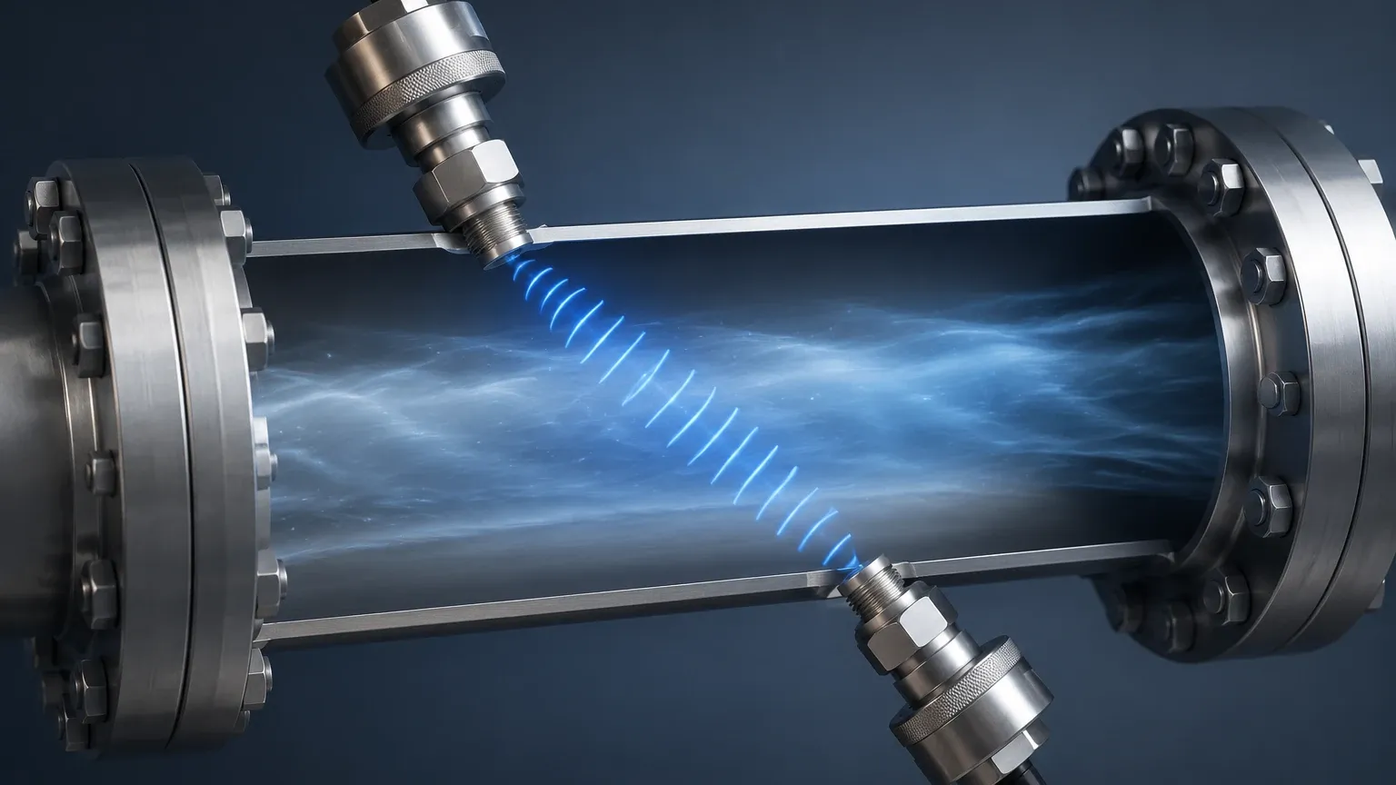
This method operates on the principle that the time it takes for an ultrasonic pulse to travel between two transducers depends on the velocity of the gas within the pipe. Two transducers are mounted on the pipe, acting as both transmitters and receivers. They send acoustic signals back and forth diagonally across the gas stream.
1. Upstream Transmission: When a pulse is sent against the flow, it is slowed down by the gas velocity.
2. Downstream Transmission: When a pulse is sent with the flow, it is accelerated by the gas velocity.
The difference between these two travel times (the "transit time") is directly proportional to the velocity of the gas. By knowing the cross-sectional area of the pipe and the gas velocity, the meter calculates the volumetric flow rate. Modern electronics then compensate for temperature and pressure to provide mass flow or standardized volume flow.
The Doppler Effect Principle
While less common for clean gas applications, the Doppler effect involves measuring the frequency shift of an ultrasonic signal reflecting off particles or bubbles within the gas stream. This is typically reserved for "dirty" gases where high concentrations of entrained solids or liquids are present. However, for most industrial natural gas, nitrogen, or compressed air applications, the Transit-Time method provides superior accuracy.
Key Evaluation Criteria for Selection
Selecting the right ultrasonic gas flowmeter requires a detailed analysis of the process conditions. Because gas is compressible and its density varies significantly with temperature and pressure, the following criteria must be confirmed before procurement.
1. Gas Composition and Velocity
The speed of sound varies depending on the gas mixture. For example, the speed of sound in methane is different from that in carbon dioxide. High-performance meters allow for the input of gas composition data to calibrate the calculations. Additionally, the velocity range (turn-down ratio) is critical; ultrasonic meters are known for high turn-down ratios, often exceeding 100:1, allowing them to measure both leak-level flows and high-velocity surges.
2. Operating Pressure and Temperature
Ultrasonic transducers must be rated for the specific environment. High-pressure applications (above 100 bar) require robust transducer housings, while high-temperature applications (above 150°C) may require specialized cooling fins or remote electronics. Conversely, at very low pressures (vacuum or near-atmospheric), the gas density may be too low to effectively transmit acoustic signals, leading to signal loss.
3. Path Configuration (Accuracy vs. Cost)
Industrial ultrasonic gas flowmeters are available in different path configurations:
* Single-Path: Cost-effective but sensitive to flow profile distortions. Best for stable, well-developed flow.
* Multi-Path (2, 3, or 4-path): Uses multiple pairs of transducers to sample different sections of the pipe. This averages out turbulence and provides high accuracy (up to 0.5% of reading), making them suitable for custody transfer.
Practical Selection Table
The following table provides a general guideline for comparing different ultrasonic gas flowmeter configurations based on typical industrial requirements.
| Feature | Single-Path Meter | Dual-Path Meter | Multi-Path (4+ Path) |
| :— | :— | :— | :— |
| Typical Accuracy | ±1.0% to 2.0% | ±0.5% to 1.0% | ±0.1% to 0.5% |
| Pipe Diameter (DN) | 25mm – 300mm | 50mm – 600mm | 100mm – 1200mm+ |
| Pressure Drop | Negligible | Negligible | Negligible |
| Installation Complexity | Low | Moderate | High |
| Primary Application | Process Monitoring | Energy Management | Custody Transfer / Fiscal |
| Turn-down Ratio | 50:1 | 100:1 | 150:1+ |
Installation Considerations
Proper installation is the most critical factor in ensuring the accuracy of an ultrasonic gas flowmeter. Unlike level measurement, where the sensor is often static above a liquid, flow measurement involves dynamic fluid mechanics.
Straight Pipe Runs
To ensure a stable flow profile, ultrasonic meters require a specific length of straight pipe both upstream and downstream of the sensor. A common engineering rule is the "10D/5D rule"—10 times the pipe diameter of straight run upstream and 5 times the diameter downstream. If the installation site has elbows, valves, or reducers closer than these distances, a flow conditioner (vane or perforated plate) may be required to eliminate swirl and turbulence.
Orientation and Alignment
For gas applications, transducers are typically mounted in the 3 o'clock and 9 o'clock positions (horizontal plane). This prevents moisture or condensate from settling on the bottom transducers and prevents gas bubbles or debris from interfering with the top transducers. Precise alignment of the transducers is mandatory; even a few millimeters of misalignment can lead to significant signal attenuation.
Acoustic Insulation
In environments with high ambient noise or where the pipe itself carries mechanical vibrations, acoustic insulation may be necessary. Ultrasonic meters operate at specific frequencies (typically 50 kHz to 200 kHz for gas). If external noise overlaps with these frequencies, the meter may struggle to distinguish the signal from the background noise.
Limitations and Common Risks
While highly versatile, the ultrasonic gas flowmeter is not a universal solution for every gas application. Engineers should be aware of the following limitations:
* Signal Attenuation in High CO2: Gases with high carbon dioxide content absorb ultrasonic energy much more readily than air or natural gas. This can "wash out" the signal, requiring higher-power transducers or lower-frequency sensors.
* Pressure Minimums: Most transit-time meters require a minimum operating pressure (often around 1 to 5 bar absolute) to ensure the gas is dense enough to carry the sound wave. Measuring gas at atmospheric pressure or under vacuum remains a challenge for this technology.
* Acoustic Noise from Valves: Pressure-regulating valves located near the meter can generate high-frequency ultrasonic noise. If this noise falls within the operating frequency of the flowmeter, it can interfere with the measurement. Locating the meter upstream of such valves is a standard best practice.
* Liquid Entrainment: While the meter can handle dry gas perfectly, significant liquid carryover (slugs of oil or water) can block the acoustic path entirely, causing the meter to fail-safe or provide erratic readings.
Frequently Asked Questions (FAQ)
Q: How often does an ultrasonic gas flowmeter need calibration?
A: Unlike mechanical meters, ultrasonic meters have no wearing parts, so their geometry does not change over time. In many process applications, a "dry calibration" or diagnostic check of the electronics every 2 to 5 years is sufficient. However, for custody transfer, local regulations may require annual wet calibration.
Q: Can I use an ultrasonic flowmeter for steam?
A: Steam is a gas, but it is high-temperature and often contains moisture (saturated steam). While specialized ultrasonic steam flowmeters exist, they require high-temperature transducers and specific signal processing to handle the noise of steam flow.
Q: Does the pipe material affect the measurement?
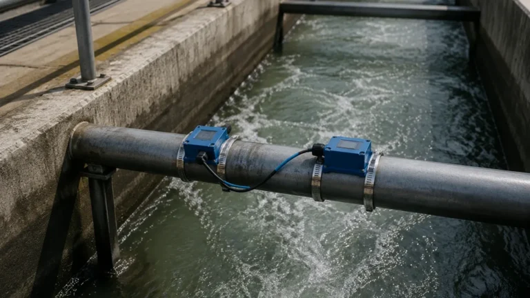
A: For "spool-piece" meters (where the meter is a pre-fabricated section of pipe), the material is factored into the design. For "clamp-on" ultrasonic meters, the pipe material, wall thickness, and internal liners significantly affect the signal. Clamp-on models are generally less accurate for gas than for liquids due to the impedance mismatch between the pipe wall and the gas.
Conclusion and Next Steps
The ultrasonic gas flowmeter represents a high-water mark in industrial instrumentation, offering a blend of precision and low maintenance that mechanical alternatives cannot match. By understanding the transit-time principle and adhering to strict installation guidelines regarding straight pipe runs and gas density, facilities can achieve highly reliable data for process control and energy accounting.
For engineers looking to integrate these systems into broader automation frameworks, it is vital to source equipment from manufacturers who understand the nuances of acoustic technology. To explore a wider range of industrial measurement solutions, including radar and ultrasonic sensors designed for challenging environments, you may review product options and application support on the Main Page. Ensuring that your flow measurement strategy aligns with your level and pressure monitoring systems will result in a more cohesive and efficient industrial operation.