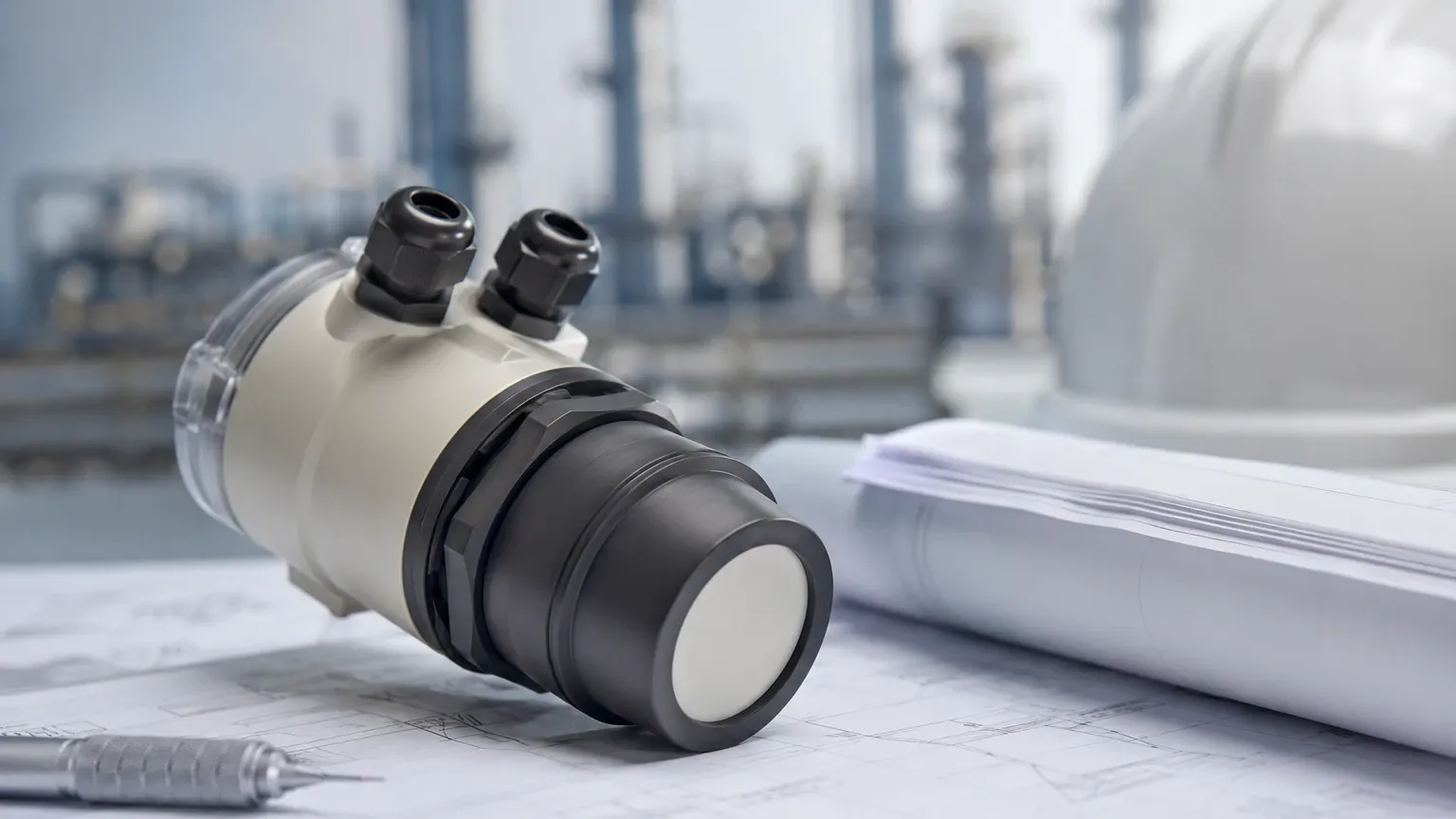
Ultrasonic Measurement Device
Ultrasonic Measurement Device
In the landscape of industrial automation and process control, the ultrasonic measurement device has established itself as a cornerstone for non-contact level monitoring. Utilizing high-frequency sound waves to determine the distance to a liquid or solid surface, these instruments provide a reliable, cost-effective, and low-maintenance solution for a diverse range of applications. From municipal water treatment facilities to complex chemical processing plants, understanding the engineering principles and selection criteria of these devices is essential for ensuring operational efficiency and safety.
As a professional manufacturer of industrial level measurement instruments, Welk provides advanced solutions designed to meet the rigors of modern industrial environments. This guide serves as a practical engineering reference for selecting, installing, and maintaining ultrasonic measurement technology.
Measurement Principles: How Ultrasonic Devices Work
The fundamental operation of an ultrasonic measurement device is based on the "Time-of-Flight" (ToF) principle. The device consists of a transducer that acts as both a transmitter and a receiver.
The Acoustic Pulse
The transducer contains a piezoelectric crystal that, when excited by an electrical pulse, vibrates at a specific ultrasonic frequency—typically between 20 kHz and 200 kHz. This vibration generates a burst of sound waves that travel through the air or gas medium toward the target material.
Echo Reflection and Detection
When the sound waves hit the surface of the medium (liquid or solid), they are reflected back toward the sensor. The transducer then switches to receiving mode to detect the returning echo. The internal electronics of the ultrasonic measurement device measure the precise time interval between the transmission of the pulse and the reception of the echo.
Calculating Distance and Level
The distance ($D$) from the sensor to the surface is calculated using the formula:
D = (c × t) / 2
Where:
* c is the speed of sound in the medium (approximately 344 m/s in air at 20°C).
* t is the measured time for the round trip.
The level of the material ($L$) in a tank is then determined by subtracting the measured distance from the total height of the tank ($H$):
L = H – D
Because the speed of sound is affected by air temperature, most high-quality ultrasonic measurement devices include an integrated temperature sensor to provide real-time compensation, ensuring accuracy across varying environmental conditions.
Key Components of an Ultrasonic Measurement Device
To function effectively in industrial settings, these devices are comprised of several critical sub-systems:
1. Transducer: The heart of the device, responsible for converting electrical energy into acoustic energy and vice versa. Materials often include PVDF, PTFE, or specialized plastics to resist chemical corrosion.
2. Signal Processing Electronics: Advanced algorithms are used to filter out noise, ignore false echoes from internal tank obstructions (like agitators or ladders), and process the signal into a usable output.
3. Housing: Usually rated IP66, IP67, or IP68, the housing protects the electronics from moisture, dust, and hazardous atmospheres.
4. Output Interface: Standard industrial outputs include 4-20mA analog signals, often with HART protocol, or digital communication via RS485 (Modbus).
Practical Selection Criteria
Choosing the right ultrasonic measurement device requires a thorough analysis of the application environment. The following table provides a general comparison of typical specifications for different industrial models.
Selection Table: Ultrasonic Device Specifications
| Feature | Standard Liquid Sensor | Long-Range Sensor | Chemical Resistant Model |
| :— | :— | :— | :— |
| Measuring Range | 0.25m to 10m | 0.5m to 30m | 0.25m to 12m |
| Accuracy | ±0.25% of FS | ±0.5% of FS | ±0.25% of FS |
| Beam Angle | 8° to 12° | 5° to 10° | 8° to 12° |
| Process Temp. | -20°C to +60°C | -40°C to +80°C | -20°C to +70°C |
| Housing Material | ABS / Nylon | Aluminum Alloy | PVDF / PTFE |
| Output Options | 4-20mA / Modbus | 4-20mA / HART | 4-20mA / Modbus |
When evaluating these options, engineers should prioritize the chemical compatibility of the wetted parts and the required range. For more detailed technical specifications and product options, engineers can refer to the Main Page for a comprehensive overview of available technologies.
Installation Considerations and Best Practices
Proper installation is the most critical factor in the performance of an ultrasonic measurement device. Even the most advanced sensor will fail to provide accurate data if positioned incorrectly.
1. The Blocking Distance (Dead Zone)
Every ultrasonic sensor has a "blocking distance" or "dead zone" immediately below the transducer face where it cannot measure. This is the time required for the transducer's mechanical vibrations to dampen before it can listen for an echo. Typically, this ranges from 0.2m to 0.8m depending on the frequency. The device must be mounted high enough so that the maximum liquid level never enters this zone.
2. Beam Path and Obstructions
The ultrasonic pulse spreads out in a cone shape (the beam angle). The entire path of this beam must be clear of obstructions such as pipes, reinforcement beams, or agitators. If an obstruction is unavoidable, many modern devices offer "false echo suppression" software to map out and ignore these static reflections.
3. Mounting Position
* Avoid the Center: In rounded tanks, do not mount the sensor in the exact center, as this can create a parabolic effect that concentrates unwanted echoes.
* Distance from Wall: A general rule is to mount the sensor at a distance from the wall equal to at least 1/6th of the tank height to avoid interference from wall seams or weld beads.
* Perpendicularity: The transducer face must be perfectly parallel to the surface of the liquid to ensure the echo returns directly to the sensor.
4. Nozzle Geometry
If the sensor is mounted on a nozzle (standpipe), the nozzle should be as short and wide as possible. If the nozzle is too long or narrow, the ultrasonic pulse may reflect off the internal walls of the pipe before reaching the tank, causing measurement errors.
Limitations and Environmental Factors
While highly versatile, the ultrasonic measurement device is not a universal solution. Certain physical conditions can attenuate or distort the sound signal:
* Heavy Foam: Thick, dense foam on the surface of a liquid can absorb the ultrasonic pulse, preventing an echo from returning. In such cases, a radar level meter or a hydrostatic transmitter may be more appropriate.
* Vacuum Conditions: Sound waves require a medium (air or gas) to travel. Ultrasonic devices cannot function in a vacuum.
* Extreme Turbulence: Rapidly moving or splashing surfaces can scatter the sound waves, leading to intermittent signal loss. This can often be mitigated using a stilling well.
* Vapor and Dust: High concentrations of heavy vapors or extremely thick dust can change the speed of sound or attenuate the signal, though many devices can be tuned to compensate for moderate levels of these factors.
Comparison: Ultrasonic vs. Radar
Engineers often choose between ultrasonic and radar (microwave) technologies. While both are non-contact, they have distinct differences:
* Cost: Ultrasonic devices are generally more budget-friendly, making them ideal for standard water and wastewater applications.
* Medium Sensitivity: Ultrasonic is affected by air temperature and turbulence; Radar is unaffected by air conditions but is sensitive to the dielectric constant of the material being measured.
* Range: Radar typically offers longer ranges (up to 70m+) and higher precision in high-pressure or high-temperature environments.
Maintenance and Troubleshooting
One of the primary benefits of an ultrasonic measurement device is the lack of moving parts, which significantly reduces maintenance requirements. However, periodic checks are recommended:
* Transducer Cleaning: In applications with high humidity or splashing, condensate or material buildup may occur on the transducer face. Wiping the face with a soft cloth and mild detergent is usually sufficient.
* Signal Strength Monitoring: Most digital ultrasonic devices provide a "Signal-to-Noise Ratio" (SNR) or echo strength value. Monitoring this can help predict when cleaning or recalibration is necessary.
Frequently Asked Questions (FAQ)
Q: Can an ultrasonic measurement device be used for solids?
A: Yes, but with limitations. Solids like powders or grains often have an uneven surface that scatters the sound waves. A higher-power sensor with a lower frequency and specialized mounting (to account for the angle of repose) is typically required.
Q: How does temperature affect the accuracy?
A: The speed of sound changes by approximately 0.17% per degree Celsius. Without compensation, a 10°C change could result in a significant error. Most Welk sensors include an internal thermistor to automatically correct for this.
Q: What is the maximum distance an ultrasonic sensor can measure?
A: Standard industrial sensors typically reach up to 15-20 meters. Specialized long-range models can reach up to 30 or 40 meters, though signal reliability decreases as distance increases due to sound attenuation in the air.
Q: Is it possible to use these devices in hazardous areas?
A: Yes, many ultrasonic measurement devices are available with Intrinsically Safe (Ex ia) or Flameproof (Ex d) certifications for use in explosive atmospheres common in the oil and gas or chemical sectors.
By understanding the acoustic principles and adhering to strict installation guidelines, engineers can leverage the ultrasonic measurement device to achieve precise and reliable level control across a multitude of industrial processes. For further assistance in selecting the correct instrument for your specific application, reviewing technical documentation on the Main Page is a recommended next step.