Vec 693
Vec 693
In the landscape of industrial automation and process control, the accuracy of level measurement is only as valuable as the reliability of the data transmission. The vec 693 represents a specific category of communication interface modules designed to bridge the gap between field-level sensors and high-level control systems. Whether used for parameter adjustment, diagnostic analysis, or continuous data logging, understanding the integration of these interface components is essential for modern plant engineering.
As industrial facilities transition toward Industry 4.0, the role of signal converters and interface adapters like the vec 693 has evolved. These devices are no longer mere accessories; they are critical nodes that ensure the precision of radar, ultrasonic, and hydrostatic sensors is reflected in the PLC (Programmable Logic Controller) or SCADA system. This guide explores the technical foundations of level measurement communication, the specific role of interface modules, and best practices for implementation in demanding environments.
Measurement Principles in Industrial Level Sensing
Before detailing the specifics of interface modules like the vec 693, it is necessary to understand the primary measurement technologies they support. Most modern level instruments rely on the "Time of Flight" (ToF) principle or hydrostatic pressure calculations.
Radar Level Measurement
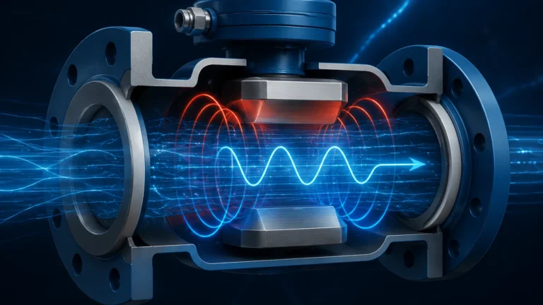
Radar level meters emit high-frequency electromagnetic waves (typically in the 26 GHz or 80 GHz range). These waves travel to the surface of the medium, reflect, and return to the sensor. The distance is calculated based on the time elapsed and the constant speed of light. Because radar waves do not require a medium for travel, they are unaffected by vacuum, high pressure, or temperature fluctuations.
Ultrasonic Level Measurement
Similar to radar, ultrasonic sensors use ToF but utilize sound waves. A transducer emits an ultrasonic pulse that reflects off the liquid or solid surface. While cost-effective, these sensors are sensitive to air temperature changes (which affect the speed of sound) and the presence of heavy foam or dust, which can attenuate the signal.
Hydrostatic Level Measurement
This method measures the pressure exerted by a liquid column. Based on the formula $P = \rho \cdot g \cdot h$ (where $P$ is pressure, $\rho$ is density, $g$ is gravity, and $h$ is height), the transmitter converts the pressure at the bottom of a tank into a level reading. This requires a stable density of the medium to maintain accuracy.
All these sensors generate a raw signal that must be processed. The vec 693 and similar interfaces allow engineers to access the internal software of these sensors to calibrate the "Zero" and "Span" points, adjust damping filters, and map the vessel geometry to eliminate false echoes.
The Role of the Vec 693 in Process Communication
The vec 693 functions primarily as a HART (Highway Addressable Remote Transducer) interface or a specialized signal converter. Its main purpose is to facilitate the exchange of data between a PC or handheld terminal and the field instrument.
In many legacy and some modern systems, the 4-20 mA analog loop carries the primary measurement value. However, the HART protocol allows digital information to be superimposed on this analog signal without interference. The vec 693 acts as the physical layer converter that allows a computer to read this digital data. This is crucial for:
1. Commissioning: Setting up the sensor parameters for the first time.
2. Diagnostics: Viewing echo curves to identify if an internal obstruction (like an agitator) is causing measurement errors.
3. Maintenance: Checking the "health" of the sensor electronics and transducer.
Technical Specifications and Selection Criteria
When selecting an interface module or a compatible level transmitter, engineers must evaluate the environmental and electrical constraints of the application. The following table provides a comparison of common interface requirements for industrial level measurement.
Table 1: Interface Selection Matrix
| Feature | Vec 693 / Standard HART Adapter | Modbus RS485 Interface | Bluetooth Integrated Modules |
| :— | :— | :— | :— |
| Primary Use | Configuration & Diagnostics | Continuous Data Integration | Mobile App Monitoring |
| Max Distance | 1,500 m (depending on cable) | 1,200 m | 25 – 50 m |
| Power Source | Loop-powered or USB-powered | External 24V DC | Internal Sensor Power |
| Protocol | HART 5/6/7 | RTU / ASCII | Proprietary / BLE |
| Hazardous Area | Requires IS Barrier | Requires Explosion-proof Housing | Often ATEX/IECEx Certified |
For those seeking integrated solutions where the transmitter and communication interface are optimized for seamless connectivity, reviewing the latest hardware options on the Main Page is recommended to ensure compatibility with existing plant infrastructure.
Installation and Integration Considerations
Correct installation of the vec 693 interface or any communication bridge is vital to prevent signal noise and data corruption. In industrial environments, electromagnetic interference (EMI) from large motors and variable frequency drives (VFDs) can disrupt low-voltage digital communication.
Wiring and Connection
The interface is typically connected in parallel with the load resistor (usually 250 ohms) of the 4-20 mA loop. It is imperative that the loop has sufficient voltage; most HART-capable transmitters require at least 12V to 18V DC at the terminals to function correctly while communicating.
Grounding and Shielding
To maintain signal integrity, twisted-pair shielded cables should be used. The shield should be grounded at only one point—typically at the control cabinet side—to avoid ground loops which can introduce significant measurement offsets.
Software Integration
Devices like the vec 693 require DTM (Device Type Manager) drivers to communicate with FDT (Field Device Tool) frame applications like PACTware or FieldCare. Ensuring that the correct DTM is installed for the specific sensor model is the most common hurdle during the commissioning phase.

Limitations and Operational Constraints
While the vec 693 provides essential connectivity, users must be aware of its operational boundaries:
* Point-to-Point vs. Multi-drop: Most standard interfaces are designed for point-to-point communication. In multi-drop configurations (where multiple sensors are on one loop), the polling address of each sensor must be uniquely configured before the interface can distinguish between them.
* Explosive Atmospheres: If the level sensor is located in a Zone 0 or Zone 1 hazardous area, the interface module must be used in conjunction with an intrinsically safe (IS) barrier. Connecting a non-certified PC or interface directly to a sensor in a hazardous area can bypass safety protections.
* Bandwidth: HART communication via an interface like the vec 693 is relatively slow (1200 baud). It is excellent for configuration but generally not suitable for high-speed control loops requiring millisecond response times.
Maintenance and Troubleshooting
If the communication via the vec 693 fails, engineers should follow a systematic diagnostic process:
1. Check Loop Resistance: Ensure there is a minimum of 230 ohms and a maximum of 600 ohms in the loop. Without enough resistance, the HART signal will be absorbed by the power supply.
2. Verify Voltage: Measure the voltage at the sensor terminals while the loop is active. A drop below the minimum operating voltage during communication is a common cause of intermittent connection loss.
3. Noise Analysis: Use an oscilloscope to check for high-frequency noise on the DC line. If noise exceeds 1.2 mV RMS in the HART frequency band, communication will likely fail.
Frequently Asked Questions (FAQ)
Q: Can the vec 693 be used with any brand of level meter?
A: If the vec 693 is a standard HART-to-USB interface, it can generally communicate with any HART-enabled device. However, full access to all parameters usually requires the specific DTM file provided by the instrument manufacturer.
Q: Does the interface affect the 4-20 mA analog signal?
A: No. The digital signal is AC-coupled and has a zero-average DC value, meaning it does not offset the analog level reading used by the PLC.
Q: Is a specialized power supply needed for the vec 693?
A: Most modern versions are powered directly via the USB port of the connected PC, but they still require the 4-20 mA loop they are monitoring to be powered by a 24V DC industrial power supply.
Conclusion
The vec 693 and its associated communication protocols remain a cornerstone of industrial level measurement. By allowing deep access to sensor logic and diagnostics, these tools ensure that level measurement systems are not just providing a number, but are providing a reliable, verified data point. For engineers looking to upgrade their current measurement capabilities or source new, high-precision transmitters with built-in advanced communication features, exploring the options available at Welk's Main Page provides a path toward more robust and transparent process control. Selecting the right combination of sensor technology and interface hardware is the first step in reducing downtime and optimizing chemical, water treatment, or oil and gas operations.