Vector Pearland
Vector Pearland
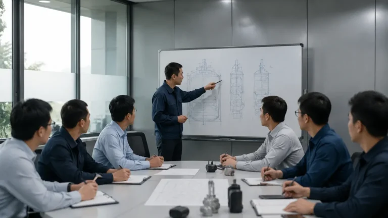
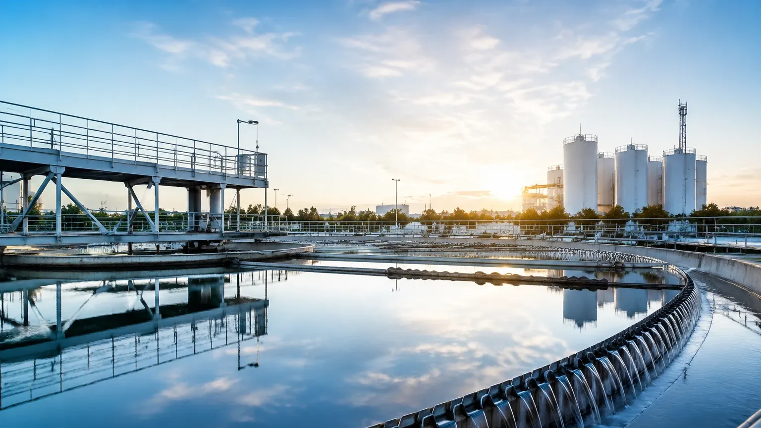
The industrial landscape of the Texas Gulf Coast, particularly around the Pearland area, serves as a global benchmark for process automation and instrumentation excellence. In this region, the term "Vector Pearland" is synonymous with the Vector Controls and Automation Group’s Gulf Coast Regional Service Center. This facility represents the intersection of high-tier engineering support and advanced hardware distribution. For professionals operating in the oil and gas, chemical processing, and water treatment sectors, understanding the technologies supported in such hubs is critical for maintaining operational efficiency and safety.
Reliable level measurement is a cornerstone of these industrial operations. Whether managing volatile hydrocarbons in a refinery or monitoring storage tanks in a municipal water facility, the selection of the correct sensing technology determines the accuracy of inventory management and the efficacy of overfill prevention systems. This guide explores the fundamental principles of level measurement, selection criteria, and the engineering standards upheld by leading solutions providers in the Pearland industrial corridor.
Fundamental Principles of Level Measurement
Before selecting an instrument, it is essential to understand the physics governing different measurement methodologies. Modern industrial level sensors generally fall into two categories: point level detection and continuous level measurement.
Radar Level Measurement (FMCW and Pulse)
Radar technology is widely regarded as the gold standard for challenging process conditions. It operates on the Time-of-Flight (ToF) principle. The sensor emits electromagnetic pulses (or a continuous wave) that travel at the speed of light. When these waves hit the surface of the medium, they are reflected back to the sensor.
* Non-Contact Radar: These devices emit signals through the air. Frequency-Modulated Continuous Wave (FMCW) radar is particularly effective because it transmits a signal with a constantly changing frequency. The difference in frequency between the transmitted and received signal is proportional to the distance. High-frequency systems (e.g., 80 GHz) offer narrow beam angles, which are ideal for avoiding internal tank obstructions like agitators.
* Guided Wave Radar (GWR): This technology uses a physical probe (rod or cable) to guide the microwave signal to the liquid surface. It is highly effective for low-dielectric liquids and applications where foam or heavy steam might scatter a non-contact signal.
Ultrasonic Level Sensors
Ultrasonic sensors use sound waves rather than electromagnetic waves. The transducer emits an ultrasonic pulse that reflects off the surface of the target. By measuring the time interval between transmission and reception, the device calculates the distance based on the speed of sound. Because the speed of sound is affected by air temperature, high-quality ultrasonic sensors, such as those manufactured by Welk, include integrated temperature compensation to maintain accuracy across varying environmental conditions.
Hydrostatic Level Transmitters
Hydrostatic measurement relies on the principle that the pressure at the bottom of a vessel is directly proportional to the height of the liquid column above it, multiplied by the specific gravity of the fluid. The formula used is $P = \rho \cdot g \cdot h$, where $P$ is pressure, $\rho$ (rho) is the density of the liquid, $g$ is the gravitational constant, and $h$ is the height. This method is exceptionally reliable for vented tanks and deep-well applications.
Magnetic Level Gauges
Magnetic level gauges (MLGs) provide a high-visibility mechanical solution. A float containing a permanent magnet moves with the liquid level inside a bypass chamber. This magnet actuates flags or rollers on an external scale. MLGs are preferred in high-pressure or high-temperature environments where electronic displays might be difficult to read or where a redundant mechanical backup is required for safety.
The Role of Regional Solutions Centers like Vector Pearland
Facilities like the Vector Pearland center are more than just warehouses; they are centers of technical excellence. In the context of the Texas Gulf Coast, these centers provide several critical functions for the process industry:
1. Application Engineering: Experts help determine if a guided wave radar or a non-contact ultrasonic sensor is better suited for a specific chemical's dielectric constant and vapor pressure.
2. Training and Certification: Many facilities offer hands-on training for technicians to ensure that instruments are calibrated and maintained according to manufacturer specifications.
3. Customization and Assembly: Large-scale projects often require customized mounting brackets, specialized seals, or integrated wireless transmitters. Local assembly ensures faster turnaround times for critical infrastructure.
For engineers looking to explore the full range of available hardware and technical documentation, visiting a comprehensive resource like the Main Page of an established manufacturer provides the necessary data to begin the specification process.
Selection Criteria for Level Measurement Instruments
Choosing the right instrument requires a systematic evaluation of the process environment. The following table provides a comparison of common technologies used in industrial applications.
| Technology | Ideal Media | Max Range (Typical) | Key Advantage | Major Limitation |
| :— | :— | :— | :— | :— |
| 80 GHz Radar | Liquids & Solids | Up to 120m | Extremely accurate; ignores obstructions | Higher initial cost |
| Ultrasonic | Water & Wastewater | 15m – 30m | Cost-effective; non-contact | Sensitive to foam and heavy vapors |
| Guided Wave Radar | Low Dielectric Fluids | 60m | Works in turbulence and foam | Physical contact with media required |
| Hydrostatic | Slurries & Water | 200m+ | Simple installation; very robust | Requires constant fluid density |
| Magnetic Gauge | Corrosive Chemicals | 6m+ | No power required for local visual | Mechanical parts can wear over time |
Installation and Engineering Considerations
Even the most advanced sensor will fail if improperly installed. When engineering a level measurement solution, particularly in the demanding environments found near Pearland, the following factors must be addressed:
Nozzle Placement and Geometry
For radar and ultrasonic sensors, the nozzle height and diameter are critical. If a nozzle is too long or narrow, it can create "ringing" or internal reflections that the sensor might mistake for a level signal. Ideally, the sensor face should protrude slightly into the tank or be set back in a way that the beam angle does not intersect the nozzle walls.
Dead Bands (Blocking Distance)
Every non-contact sensor has a "dead band" or "blocking distance" directly below the transducer where measurement is impossible. This is the time required for the transducer to stop vibrating from the transmission pulse and begin "listening" for the echo. Engineers must ensure that the maximum expected liquid level does not enter this zone.
Environmental Factors
In the Gulf Coast, humidity and ambient temperature fluctuations are extreme. For ultrasonic sensors, this requires robust temperature compensation. For hydrostatic sensors, the vent tube in the cable must be protected from moisture ingress using desiccant filters to prevent offset errors in pressure readings.
Limitations and Technical Challenges
While modern instrumentation is highly advanced, certain physical limitations remain:
* Dielectric Constants ($ε_r$): Radar relies on the reflectivity of the medium. Materials with very low dielectric constants (like certain oils or liquefied gases) reflect very little energy. In these cases, Guided Wave Radar or high-sensitivity FMCW radar is required.
* Vapor Layers and Gas Blanketing: In pressurized tanks, the composition of the gas space can change the speed of sound, making ultrasonic measurement inaccurate unless the gas composition is constant and known.
* Agitation and Turbulence: Rapidly moving surfaces can scatter signals. Using a stilling well or a bypass chamber can isolate the measurement area from turbulence, ensuring a stable reading.
Frequently Asked Questions (FAQ)
Q: Why is 80 GHz radar becoming the industry standard over 26 GHz?
A: The higher frequency allows for a much smaller antenna and a narrower beam angle (often as low as 3 degrees). This makes it easier to install in small nozzles and prevents the signal from hitting tank walls or internal structures like ladders and agitators.
Q: Can hydrostatic transmitters be used in pressurized tanks?
A: Yes, but you must use a differential pressure (DP) approach. One sensor measures the pressure at the bottom, and a second sensor measures the gas pressure at the top. The system subtracts the top pressure to find the true hydrostatic head of the liquid.
Q: How often should level instruments be calibrated?
A: Calibration frequency depends on the criticality of the application and the stability of the technology. Radar and ultrasonic sensors are generally very stable and may only require verification once a year. Hydrostatic sensors in corrosive media may require more frequent checks to ensure the diaphragm has not degraded.
Q: What is the impact of foam on level measurement?
A: Foam can either absorb or reflect signals depending on its density and the technology used. Ultrasonic signals are often absorbed by foam, leading to a loss of echo. Guided Wave Radar is typically the best choice for penetrating foam to find the true liquid level.
Conclusion
The expertise found at regional hubs like Vector Pearland underscores the importance of localized support and technical precision in industrial automation. By understanding the underlying physics of radar, ultrasonic, and hydrostatic measurement, engineers can make informed decisions that enhance plant safety and efficiency. Whether you are upgrading a legacy system or designing a new facility, selecting the right level measurement technology is a critical step in achieving operational excellence. For further technical specifications and product selection tools, professional engineers are encouraged to consult the Main Page for detailed instrumentation resources.