Vega Level Sensor
Vega Level Sensor
In the landscape of industrial process automation, the selection of a level measurement instrument is a critical decision that impacts safety, efficiency, and product quality. Among the most recognized names in the industry, the Vega level sensor portfolio represents a high standard for precision and reliability. These instruments are designed to handle the complexities of liquid and bulk solid measurement across diverse sectors, including chemical processing, water and wastewater management, food and beverage production, and the oil and gas industry.
Understanding the technical nuances of these sensors is essential for engineers and procurement specialists. This guide examines the core measurement principles, application criteria, and installation best practices associated with these technologies to ensure optimal performance in demanding environments.
Measurement Principles of Vega Level Sensors
To select the correct instrument, one must first understand the physics behind the measurement. Vega utilizes several distinct physical principles to cater to different process conditions.
Non-Contact Radar (FMCW and Pulse)
Non-contact radar is perhaps the most versatile technology in the Vega level sensor lineup. These sensors emit high-frequency microwave signals toward the medium. The signals are reflected by the product surface and received back by the antenna. The sensor calculates the distance based on the time-of-flight of the signal.
Modern radar sensors, such as the 80 GHz variants, offer a significant advantage over older 26 GHz or 6 GHz models. The higher frequency allows for a much narrower beam angle, which minimizes interference from internal tank obstructions like agitators, heating coils, or ladders. This precision makes it possible to measure accurately even in narrow vessels or through small mounting nozzles.
Guided Wave Radar (GWR)
Guided Wave Radar uses Time Domain Reflectometry (TDR). Unlike non-contact radar, GWR sensors send microwave pulses along a mechanical probe (cable or rod). This probe guides the signal directly to the surface of the medium. When the pulse hits the surface, the change in the dielectric constant causes a reflection.
This technology is exceptionally robust against physical disturbances. Because the signal is contained along the probe, it is unaffected by foam, heavy dust, or turbulent surfaces. It is also the preferred method for interface measurement—for example, detecting the boundary layer between oil and water in a separator tank.
Ultrasonic Level Measurement
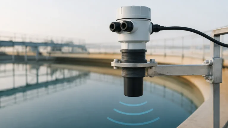
Ultrasonic sensors function by emitting sound pulses in the ultrasonic range. The time taken for the sound wave to travel to the surface and back determines the level. While cost-effective, ultrasonic sensors are sensitive to environmental factors. Changes in air temperature, pressure, and the presence of vapors or gases can alter the speed of sound, potentially leading to measurement errors. They are best suited for simple water applications or open-air basins where conditions remain relatively stable.
Hydrostatic Pressure
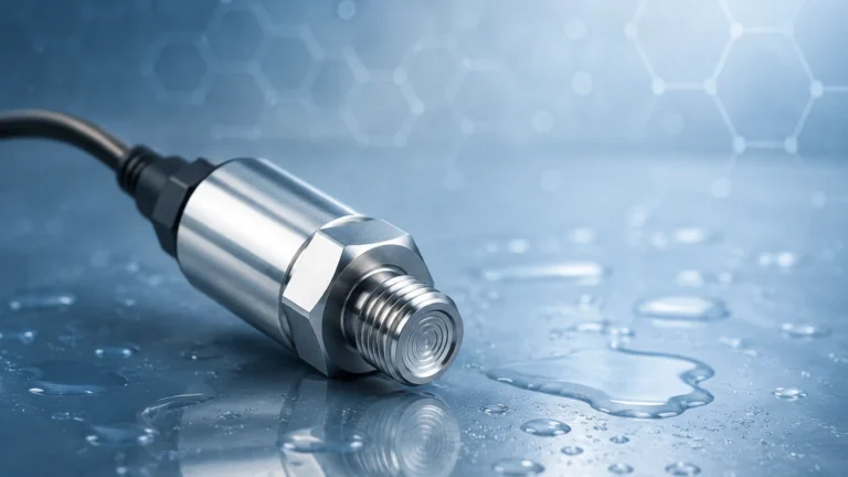
For vented or pressurized tanks, hydrostatic pressure sensors measure the weight of the liquid column above the sensor diaphragm. The relationship is defined by the formula $P = \rho gh$ (Pressure = density × gravity × height). These sensors are highly reliable for liquids with constant density and are often used in deep wells or tall storage tanks where top-mounting a radar sensor is impractical.
Key Evaluation Criteria for Sensor Selection
Choosing a Vega level sensor requires a detailed analysis of the application's physical and chemical properties. Engineers should evaluate the following factors:
1. Media Dielectric Constant (εr): Radar signals rely on the dielectric properties of the material. Materials with low dielectric constants (like liquid gases or hydrocarbons) reflect less energy. In these cases, Guided Wave Radar or high-sensitivity non-contact radar is necessary.
2. Process Temperature and Pressure: Extreme temperatures (up to +450°C) or high pressures (up to 160 bar / 2320 psi) require specialized sensor housings and seal materials to prevent instrument failure.
3. Vessel Geometry: The height and diameter of the tank, as well as the presence of internal structures, dictate the required beam angle and mounting position.
4. Material State: Is the medium a liquid, a slurry, or a bulk solid? Bulk solids require sensors capable of handling dusty environments and uneven surface profiles (the angle of repose).
Practical Selection Table
The following table provides a general guideline for matching sensor types to common industrial scenarios:
| Application Type | Recommended Technology | Key Advantage | Limitation |
| :— | :— | :— | :— |
| Corrosive Chemicals | Non-contact Radar (80 GHz) | No contact with media; PTFE seals | High initial cost |
| Interface (Oil/Water) | Guided Wave Radar | High precision at boundaries | Probe can accumulate buildup |
| Open Water Channels | Ultrasonic | Low cost; easy installation | Affected by wind and fog |
| Foaming Liquids | Guided Wave Radar | Signal penetrates foam | Requires top-down mounting |
| Bulk Solids (Silos) | 80 GHz Radar | Penetrates dust; narrow beam | Requires aiming flanges |
| Deep Well / Borehole | Hydrostatic Pressure | Submersible; simple setup | Density changes affect accuracy |
Installation Considerations and Best Practices
Proper installation is as critical as selecting the right sensor. Even the most advanced Vega level sensor can provide inaccurate data if mounted incorrectly.
Avoiding the Dead Zone (Blocking Distance)
Every sensor has a "dead zone" or blocking distance near the antenna or probe tip where measurements are not possible. For radar sensors, this is usually between 50 mm and 250 mm. Ensure the maximum fill level of the tank does not enter this zone to avoid signal loss or "lock-on" at the top of the tank.
Mounting Position
A sensor should never be mounted in the center of a tank, as this can lead to multiple reflections (parabolic effect) that confuse the signal processing. Similarly, sensors should be kept away from the tank wall to prevent interference. The ideal position is typically 1/3 of the tank radius from the outer wall.
Nozzle Design
For non-contact radar, the mounting nozzle should be as short as possible. If the nozzle is too long or has internal burrs, it can create "false echoes" that the sensor might mistake for the actual product level. If long nozzles are unavoidable, sensors with higher frequencies (80 GHz) are better equipped to handle them due to their focused beam.
Signal Optimization
In many modern sensors, software tools allow for "false signal suppression." This process involves mapping the empty tank to identify static reflections from internal pipes or agitators. Once mapped, the sensor's electronics can ignore these static reflections and focus solely on the moving level of the product.

Limitations and Common Risks
While highly advanced, no single technology is a universal solution. Users should be aware of the following risks:
* Build-up and Coating: In Guided Wave Radar, viscous products can coat the probe. While many sensors feature compensation for this, extreme buildup can eventually bridge the signal to the tank wall, causing a false high-level reading.
* Vacuum Conditions: Ultrasonic sensors cannot function in a vacuum because sound waves require a medium (air/gas) to travel. Radar is the preferred choice for vacuum applications.
* Vapor and Condensation: While radar is generally unaffected by vapor, heavy condensation on the antenna of a non-contact sensor can attenuate the signal. Selecting a sensor with a convex or encapsulated antenna helps moisture drip off, maintaining signal integrity.
Integrating Professional Solutions
For organizations looking to optimize their process control, it is often beneficial to compare specialized brands with broader industrial offerings. While the Vega level sensor is a premier choice for many, manufacturers like Welk provide a range of radar level meters, ultrasonic sensors, and hydrostatic transmitters designed for high-performance industrial automation. To explore a wide variety of technical specifications and find the right fit for your specific infrastructure, you can Review product options and application support on our Main Page.
Frequently Asked Questions (FAQ)
Q: Can a radar sensor measure through a plastic tank lid?
A: Yes, non-contact radar signals can penetrate non-conductive materials like plastic, fiberglass, or glass. This allows for measurement without opening the vessel, which is ideal for hazardous chemicals.
Q: How does 80 GHz radar differ from 26 GHz radar?
A: The primary difference is the beam angle. An 80 GHz sensor has a much narrower beam (approximately 3° to 4°), whereas a 26 GHz sensor might have a beam of 10° or more. The narrower beam makes it easier to avoid internal obstructions and allows for smaller process fittings.
Q: What maintenance is required for these sensors?
A: Non-contact sensors are virtually maintenance-free because they have no moving parts and do not touch the media. Guided wave probes should be inspected periodically for physical damage or excessive material buildup if the media is particularly viscous.
Q: Is it possible to use these sensors in explosive atmospheres?
A: Yes, most industrial level sensors are available with ATEX, IECEx, or FM certifications for use in hazardous areas. It is vital to verify the specific Ex-rating required for your zone before procurement.
Conclusion
The implementation of a Vega level sensor provides a robust foundation for process safety and inventory management. By understanding the underlying principles—whether radar, ultrasonic, or hydrostatic—and adhering to strict installation guidelines, facilities can achieve high-precision measurements even in the most challenging conditions. When evaluating your next project, consider the specific environmental constraints and consult technical references to ensure the selected technology aligns with your long-term operational goals.