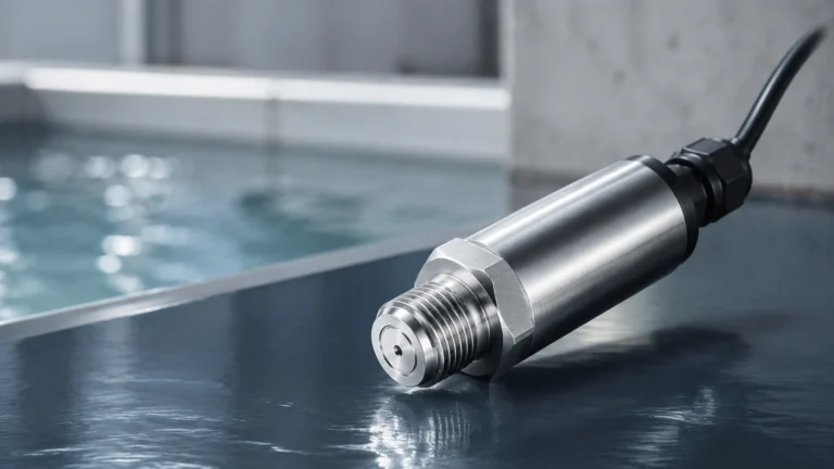
Vega Tool
Vega Tool
In the modern landscape of industrial automation, the precision of level measurement is no longer solely dependent on the hardware sensor installed on a tank or silo. The software and interface tools used to calibrate, monitor, and troubleshoot these devices—often referred to in the industry context of a vega tool or similar configuration software—are equally critical. These tools allow engineers to bridge the gap between raw physical data and actionable process control.
For professionals managing complex liquid or solid inventories, understanding the functional capabilities of configuration interfaces is essential for maintaining system integrity. Whether utilizing a specialized vega tool for high-end radar sensors or universal DTM (Device Type Manager) software for a broad range of instruments, the goal remains the same: ensuring that the level transmitter accurately reflects the physical state of the vessel. For a comprehensive overview of industrial measurement technologies, you can visit the Main Page of our product catalog.
Measurement Principles and the Need for Configuration
Before selecting or utilizing a configuration tool, it is necessary to understand the underlying measurement principles of the instruments they support. Most industrial level meters operate on one of three primary physical principles: Time of Flight (ToF), Pressure, or Capacitance.
Radar and Ultrasonic (Time of Flight)
Radar and ultrasonic sensors emit a signal (electromagnetic or sound) that reflects off the surface of the medium. The sensor measures the time it takes for the pulse to return.
* Radar: Uses high-frequency microwave pulses (typically 6 GHz, 26 GHz, or 80 GHz). It is unaffected by vacuum, pressure, or temperature fluctuations.
* Ultrasonic: Uses sound waves. It is cost-effective but sensitive to air temperature changes and heavy foam.
Why a tool is required: These sensors do not just "work" out of the box for every application. A vega tool or equivalent software is used to perform "False Echo Suppression." This involves recording the internal reflections caused by agitators, ladders, or weld seams within a tank and telling the sensor to ignore them, focusing only on the true product surface.
Hydrostatic Pressure
Hydrostatic transmitters measure the pressure exerted by a liquid column. The pressure is proportional to the height of the liquid and its density ($P = \rho gh$).
Why a tool is required: To accurately convert pressure into level, the tool must be used to input the specific gravity of the liquid and the mounting offset of the sensor. Without precise parameterization, density changes can lead to significant measurement errors.
The Role of the Vega Tool in Process Optimization
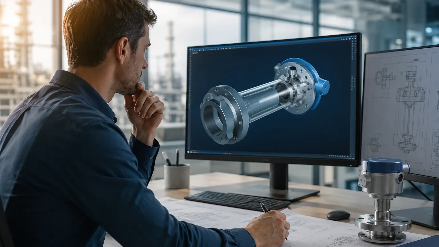
In the context of high-precision instrumentation, a vega tool typically refers to the ecosystem of adjustment modules (like the PLICSCOM) and software (like PACTware or VEGA Inventory System). These components serve several vital functions in a B2B industrial environment.
1. Commissioning and Parameterization
During the initial setup, the tool allows the technician to define the "Zero" and "Span" points. For a tank that is 10 meters (approx. 32.8 feet) high, the tool maps the 4mA signal to 0% and the 20mA signal to 100%. Advanced tools also allow for the input of tank geometry (spherical, cylindrical, or irregular) to provide volume output rather than just distance.
2. Diagnostics and Signal Analysis
Modern tools provide a visual representation of the "Echo Curve." By looking at this curve, an engineer can see the strength of the return signal. If the signal is weak due to turbulence or dust, the tool can be used to increase the sensitivity or adjust the damping filters to stabilize the reading.
3. Asset Management and Documentation
Regulatory compliance in industries like chemicals and pharmaceuticals requires documented proof of calibration. Configuration tools can generate reports that log all internal settings, providing a "snapshot" of the instrument’s state at the time of commissioning.
Selection Criteria for Level Measurement Interfaces
Choosing the right interface method depends on the environment, the frequency of adjustment, and the existing control architecture. The following table compares common methods used to interface with industrial level meters.
| Interface Method | Connectivity | Best For | Pros | Cons |
| :— | :— | :— | :— | :— |
| Local Display/Keypad | Physical Attachment | Quick field checks | No external hardware needed | Difficult access in tall silos |
| PC Software (PACTware/DTM) | USB/HART Modem | Detailed commissioning | Full visualization of echo curves | Requires laptop and cables |
| Mobile App | Bluetooth | Hard-to-reach areas | Wireless up to 25m (82ft) | Limited by signal interference |
| Remote Web Portal | Ethernet/Cellular | Inventory management | Access from anywhere | Requires cloud infrastructure |
Installation and Commissioning Considerations
When using a configuration tool to set up a new sensor, such as a Welk radar level meter, several physical and logical factors must be addressed to ensure the software and hardware communicate effectively.
Physical Mounting
The sensor must be mounted in a position where the signal beam has a clear path to the liquid surface. For radar sensors, this usually means avoiding the center of the tank (to avoid multiple reflections) and staying away from the tank wall (to avoid signal attenuation).
Communication Protocols
Most industrial tools communicate via HART (Highway Addressable Remote Transducer). This protocol superimposes a digital signal on top of the standard 4-20mA analog loop. To use a vega tool or PC-based software, a HART modem is required to translate the signal for the computer. Alternatively, newer systems utilize IO-Link for seamless integration into Industry 4.0 environments.
Wiring and Power
Ensure the loop power is sufficient. Many radar transmitters require a minimum of 12V to 35V DC. If the voltage drops too low when the HART modem is connected, communication will fail, and the tool will not be able to detect the device.
Limitations and Common Risks
While a vega tool provides immense power to the user, there are inherent risks and limitations in the digital configuration of level instruments.
* Security Risks: Wireless tools (Bluetooth) must be protected by strong passwords. Unauthorized access to a level meter's parameters could lead to tank overfills or process shutdowns.
* Compatibility Issues: Not all DTMs work with all versions of PACTware. It is vital to ensure that the device driver (DTM) matches the specific firmware version of the hardware sensor.
* Environmental Interference: In heavy industrial zones, electromagnetic interference (EMI) can disrupt the communication between the tool and the sensor, leading to corrupted data transfers during calibration.
* Over-Reliance on Software: A tool can "mask" a poor physical installation. For example, if a sensor is mounted over a fill pipe, software mapping can ignore the pipe, but the overall signal strength will be significantly reduced, leading to potential failure during high-turbulence events.
Frequently Asked Questions (FAQ)
Q: Can I use one brand's configuration tool for another brand's sensor?
A: Generally, yes, if both follow the FDT/DTM (Field Device Tool) standard. However, specific advanced features like deep-level echo analysis are often proprietary to the manufacturer’s specific DTM.
Q: What is the difference between a DTM and an EDD?
A: An EDD (Electronic Device Description) is a text-based file that describes device parameters. A DTM (Device Type Manager) is more like a printer driver; it provides a graphical user interface (GUI) and more advanced diagnostic capabilities.
Q: How often should I use the tool to check my sensors?
A: For critical safety applications (SIL-rated), a proof test using the configuration tool should be performed annually. For general monitoring, a check every 2-3 years or when process conditions change is sufficient.
Conclusion
The integration of sophisticated software like the vega tool into the workflow of process engineers has transformed level measurement from a manual task into a data-driven science. By understanding the measurement principles of radar, ultrasonic, and pressure sensors, and by effectively utilizing configuration interfaces, facilities can achieve higher accuracy, improved safety, and reduced downtime.
When selecting your next level measurement solution, consider not only the durability of the sensor but also the robustness of the tools provided for its management. For more information on high-performance level measurement hardware and integrated solutions, please explore our Main Page.