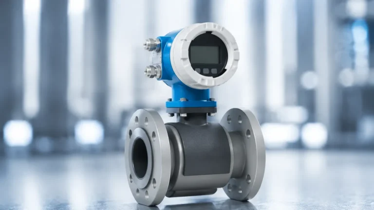
Vortex Flow Meter Pressure Drop Steam Applications Datasheet
Vortex Flow Meter Pressure Drop Steam Applications Datasheet
In industrial steam management, the selection of flow measurement technology is a critical decision that impacts both operational efficiency and energy costs. Vortex flow meters have emerged as the industry standard for steam applications due to their lack of moving parts, high temperature tolerance, and long-term stability. However, a critical technical parameter that engineers must evaluate is the permanent pressure loss—or pressure drop—introduced by the meter. This article provides a comprehensive technical overview of the vortex flow meter pressure drop steam applications datasheet, detailing the measurement principles, selection criteria, and installation requirements necessary for optimized steam system performance.
Measurement Principle: The Von Kármán Effect
Before evaluating pressure drop data, it is essential to understand how a vortex flow meter operates. The device functions based on the Von Kármán effect. When a fluid—in this case, saturated or superheated steam—encounters an unstreamlined object known as a "bluff body" or "shedder bar" placed across the flow path, it cannot follow the contours of the object on both sides simultaneously.
As the steam flows past this bluff body, layers of the fluid are separated and curled into vortices (eddies) that are shed alternately from each side of the body. The frequency at which these vortices are shed is directly proportional to the velocity of the steam flow. The relationship is defined by the Strouhal number ($St$):
$$f = \frac{St \cdot V}{d}$$
Where:
- $f$ is the vortex shedding frequency.
- $St$ is the Strouhal number (a constant for a specific bluff body shape over a wide range of Reynolds numbers).
- $V$ is the velocity of the fluid.
- $d$ is the width of the bluff body.
Because the frequency is linear to the velocity, vortex meters provide an accurate volumetric flow rate. In steam applications, where density varies with pressure and temperature, multivariable vortex meters often include integrated pressure and temperature sensors to calculate mass flow in real-time.
Understanding Pressure Drop in Steam Systems
The introduction of a bluff body into the steam line inevitably creates a restriction. This restriction results in a permanent pressure drop ($ \Delta P $). In steam distribution, excessive pressure drop is undesirable for several reasons:
1. Energy Loss: A drop in pressure represents a loss of enthalpy, reducing the work potential of the steam at the point of use.
2. Boiler Loading: To compensate for downstream pressure drops, boilers may need to operate at higher pressures, increasing fuel consumption and thermal stress.
3. Phase Changes: In saturated steam systems, a significant pressure drop can trigger partial condensation, leading to wet steam which is less efficient and can cause water hammer.
Calculating the Pressure Drop
A typical vortex flow meter pressure drop steam applications datasheet will provide formulas or coefficients to estimate the loss. The pressure drop is generally proportional to the density of the steam and the square of the velocity:
$$\Delta P = K \cdot \rho \cdot V^2$$
Where:
- $K$ is a pressure loss coefficient specific to the meter design.
- $\rho$ is the fluid density ($kg/m^3$).
- $V$ is the flow velocity ($m/s$).
Engineers should note that while a smaller meter size (reduced bore) may be more sensitive to low flow rates, it will significantly increase the pressure drop compared to a full-bore meter of the same line size.
Technical Specifications: Typical Datasheet Values
When reviewing a vortex flow meter pressure drop steam applications datasheet, the following technical specifications are standard for high-quality industrial instruments, such as those provided by Welk. These parameters ensure the meter can withstand the harsh environment of a steam header.
| Parameter | Specification (Metric) | Specification (Imperial) |
| :— | :— | :— |
| Accuracy (Steam) | ±1.5% of Rate | ±1.5% of Rate |
| Repeatability | 0.2% | 0.2% |
| Temperature Range | -40°C to +350°C | -40°F to +662°F |
| Maximum Pressure | Up to 40 bar (Standard) | Up to 580 psi (Standard) |
| Turndown Ratio | 10:1 to 30:1 | 10:1 to 30:1 |
| Body Material | 304 or 316 Stainless Steel | 304 or 316 Stainless Steel |
| Outputs | 4-20mA, Pulse, HART, RS485 | 4-20mA, Pulse, HART, RS485 |
For specific model availability and detailed engineering support, you may Review product options and application support on our main page.
Sizing and Selection for Steam Applications
Selecting the correct meter size is more complex than simply matching the pipe diameter. Steam flow rates vary significantly between peak production and idle periods. Proper sizing involves balancing the "Low Flow Cut-off" with the maximum allowable pressure drop.
Saturated vs. Superheated Steam
- Saturated Steam: The density is linked directly to the pressure. A datasheet for saturated steam will often provide a lookup table for mass flow based on operating pressure.
- Superheated Steam: Because temperature and pressure are independent, a multivariable meter with both sensors is required to ensure the pressure drop calculations and mass flow readings remain accurate as the steam properties change.
Reynolds Number Constraints
Vortex meters require a turbulent flow profile to shed vortices reliably. This is measured by the Reynolds Number ($Re$). Most meters require $Re > 10,000$ to maintain accuracy. If the steam velocity is too low, the shedding becomes erratic, and the meter will show a zero-flow condition even if steam is moving through the pipe.
Installation Considerations for Steam
To minimize the impact of pressure drop and ensure the accuracy of the vortex shedding frequency, strict installation guidelines must be followed.
1. Straight Pipe Runs: To achieve a fully developed flow profile, a minimum of 10D (10 times the pipe diameter) of straight pipe is required upstream, and 5D is required downstream of the meter. If there are multiple elbows or valves upstream, this requirement may increase to 20D or 30D.
2. Steam Trapping: Water droplets in steam (wet steam) can erode the bluff body over time and interfere with the sensor's ability to detect vortices. A steam trap should be installed upstream of the meter to remove condensate.
3. Insulation: The meter body and the adjacent piping should be insulated to prevent heat loss and condensation, which can affect density calculations and pressure drop accuracy.
4. Orientation: For steam, the meter is ideally installed in a horizontal line. If installed vertically, the flow must be upward to ensure the pipe remains full and any condensate can drain away naturally.

Limitations and Risks
While highly effective, vortex flow meters have specific limitations that must be addressed during the design phase:
- Vibration Sensitivity: Since the sensors detect pressure fluctuations from vortices, high levels of pipeline vibration can be misinterpreted as flow. Modern meters use digital signal processing (DSP) to filter out vibration, but excessive mechanical noise should still be avoided.
- Permanent Pressure Loss: As discussed, the bluff body is a permanent obstruction. In low-pressure steam systems (e.g., 1 bar / 15 psi), the pressure drop across the meter might be a significant percentage of the total system pressure.
- Minimum Velocity: Vortex meters cannot measure "zero flow." There is always a minimum velocity (typically 4-6 m/s for steam) below which the meter cannot detect vortices.
Practical Selection Table: Flow Ranges for Saturated Steam
This table provides an estimate of flow ranges for common pipe sizes at an operating pressure of 7 bar (approx. 100 psi). Note that the pressure drop increases as the flow approaches the maximum limit.
| Pipe Size (DN) | Pipe Size (Inches) | Min Flow (kg/h) | Max Flow (kg/h) | Typical $\Delta P$ at Max Flow |
| :— | :— | :— | :— | :— |
| DN25 | 1" | 25 | 250 | 0.15 bar |
| DN50 | 2" | 100 | 1,100 | 0.18 bar |
| DN80 | 3" | 220 | 2,500 | 0.20 bar |
| DN100 | 4" | 380 | 4,200 | 0.22 bar |
| DN150 | 6" | 850 | 9,500 | 0.25 bar |
| DN200 | 8" | 1,500 | 17,000 | 0.28 bar |
Frequently Asked Questions (FAQ)
Q: Can a vortex flow meter be used for wet steam?
A: While they can function, wet steam reduces accuracy because the meter is calibrated for a single-phase fluid. The presence of water droplets changes the effective density and can cause "slugging" against the bluff body. Proper upstream trapping is highly recommended.
Q: How does the pressure drop of a vortex meter compare to an orifice plate?
A: Generally, a vortex meter has a lower permanent pressure loss than an orifice plate for the same flow rate. This makes vortex meters a more energy-efficient choice for long-term steam monitoring.
Q: Is there any maintenance required for the bluff body?
A: Because there are no moving parts, the bluff body does not "wear out" in the traditional sense. However, in systems with high-velocity steam and particulates, erosion can occur over several years, which may slightly shift the Strouhal number and affect accuracy.
Q: What happens if I install the meter backwards?
A: The bluff body is designed with a specific geometry to shed vortices in one direction. Installing it backwards will result in significant measurement errors and potentially unstable readings.
Conclusion
Consulting a vortex flow meter pressure drop steam applications datasheet is a fundamental step for any utility engineer or system designer. By understanding the relationship between flow velocity, steam density, and the resulting pressure loss, facilities can select an instrument that provides the necessary data for energy management without compromising system pressure. For professional-grade instrumentation and customized measurement solutions, visit our Main Page to explore our full range of industrial sensors and transmitters.
Download Vortex Flow Meter Pressure Drop Steam Applications Datasheet as a PDF