Vortex Flow Sensor
Vortex Flow Sensor
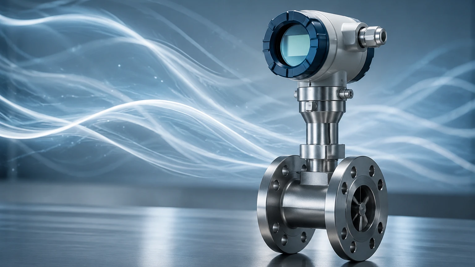
In the landscape of industrial process control, the vortex flow sensor stands as one of the most versatile and reliable instruments for measuring the flow rate of liquids, gases, and steam. Based on the principle of vortex shedding, these sensors offer a robust solution for applications where moving parts are undesirable and long-term stability is paramount. While often categorized alongside other flow technologies, the vortex flow sensor is uniquely suited for high-temperature and high-pressure environments, making it a staple in power generation, chemical processing, and HVAC systems.
This guide provides a comprehensive technical overview of vortex flow sensors, detailing their operational principles, selection criteria, and installation requirements to assist engineers in optimizing their process loops.
Understanding the Measurement Principle: The Karman Vortex Street
The operation of a vortex flow sensor is rooted in fluid dynamics, specifically a phenomenon known as the Karman Vortex Street. When a fluid—whether liquid, gas, or saturated steam—encounters an obstruction in its path, it cannot maintain a laminar flow pattern.
Inside the sensor body, a non-streamlined object called a "bluff body" or "shedder bar" is placed perpendicular to the flow direction. As the fluid flows past this bluff body, it is forced to separate. Because the body is not aerodynamic, the fluid layers cannot rejoin immediately, leading to the formation of alternating low-pressure eddies, or vortices, on downstream sides of the bar.
The Mathematical Relationship
The frequency ($f$) at which these vortices are shed is directly proportional to the velocity ($v$) of the fluid. This relationship is defined by the Strouhal number ($St$), a dimensionless parameter that remains constant over a wide range of Reynolds numbers. The formula is expressed as:
f = St × (v / d)
Where:
* f is the vortex shedding frequency.
* St is the Strouhal number (specific to the bluff body shape).
* v is the fluid velocity.
* d is the width of the bluff body.
* V (Volumetric Flow) = A (Pipe Area) × v
Because the shedder bar's dimensions and the pipe's cross-sectional area are fixed, the electronics within the sensor can calculate the volumetric flow rate simply by counting the frequency of the pressure pulses generated by the vortices. These pulses are typically detected by a piezoelectric crystal or a stress sensor embedded within or behind the shedder bar.
Key Components and Design
A standard industrial vortex flow sensor consists of three primary elements:
1. The Meter Body: Usually constructed from stainless steel (304 or 316) or high-nickel alloys, the body houses the flow passage and the bluff body. It is designed to withstand the process pressure and temperature.
2. The Shedder Bar (Bluff Body): This is the heart of the sensor. Its shape (triangular, rectangular, or D-shaped) is engineered to produce strong, detectable vortices across a broad range of flow velocities.
3. The Sensor and Transmitter: The sensor detects the mechanical oscillations or pressure fluctuations. The transmitter then converts these signals into a standard industrial output, such as a 4-20mA signal, pulse output, or digital protocols like HART, Modbus, or Foundation Fieldbus.
Selection Criteria for Industrial Applications
Choosing the correct vortex flow sensor requires a detailed understanding of the process media and environmental conditions. Unlike simple mechanical meters, vortex sensors are sensitive to fluid density and Reynolds numbers.
Fluid State and Properties
* Saturated and Superheated Steam: Vortex sensors are the industry standard for steam measurement because they lack moving parts that could wear out in high-velocity steam lines.
* Clean Liquids: They work exceptionally well with water, chemicals, and solvents with low viscosity (typically below 10-15 centipoise).
* Gases: Compressed air, nitrogen, and natural gas are common applications, provided the gas density is sufficient to trigger the sensor at the required flow rates.
Selection Table: Application Suitability
| Criteria | Liquid Applications | Gas Applications | Steam Applications |
| :— | :— | :— | :— |
| Velocity Range | 0.5 – 7 m/s | 5 – 60 m/s | 5 – 70 m/s |
| Accuracy | ±0.75% to ±1.0% of rate | ±1.0% to ±1.5% of rate | ±1.0% to ±2.0% of rate |
| Temperature Range | -40°C to +260°C | -40°C to +327°C | Up to +450°C (High-temp models) |
| Pressure Loss | Moderate | Low | Low to Moderate |
| Viscosity Limit | < 10 cP preferred | N/A | N/A |
Temperature and Pressure Compensation
Since the vortex sensor measures volumetric flow, changes in temperature and pressure can significantly affect the mass flow of gases and steam. Multivariable vortex flow sensors include integrated pressure and temperature sensors to provide real-time compensated mass flow readings, eliminating the need for separate external transmitters and flow computers.
Installation Best Practices
To ensure the accuracy of a vortex flow sensor, the flow profile entering the meter must be fully developed and free of swirls or turbulence. Proper installation is the most critical factor in instrument performance.
Straight Pipe Requirements
Turbulence caused by valves, elbows, or reducers can interfere with vortex formation. Engineers should adhere to the following minimum straight-run requirements:
* Upstream: Minimum 10 to 20 pipe diameters (D) of straight pipe, depending on the preceding obstruction (e.g., two elbows in different planes require more distance).
* Downstream: Minimum 5 pipe diameters (D) of straight pipe after the sensor.
Orientation and Piping
* Vertical vs. Horizontal: Vortex sensors can be installed in any orientation. However, for liquid applications, the flow should be upward in vertical pipes to ensure the pipe remains completely full. For steam applications, horizontal installation is preferred to prevent condensate buildup against the shedder bar.
* Alignment: The sensor must be centered precisely with the adjacent piping. Gaskets should never protrude into the flow stream, as this creates parasitic vortices that cause measurement errors.
* Vibration: While modern sensors use digital signal processing (DSP) to filter out noise, excessive pipe vibration can still mimic vortex frequencies. Sensors should be installed in stable piping sections or supported with vibration-dampening brackets.
Limitations and Operating Constraints
While highly effective, vortex flow sensors are not universal solutions. Understanding their limitations prevents costly misapplications.
1. Low Flow Cut-off: Below a certain velocity (the "threshold velocity"), the energy of the vortices is too weak to be detected. This means vortex meters cannot measure zero flow or very slow leakages.
2. Reynolds Number: The accuracy of the Strouhal number depends on a Reynolds number typically above 10,000 to 20,000. If the fluid is too viscous or the flow is too slow (laminar flow), the meter will not function correctly.
3. Pressure Drop: The bluff body creates a permanent pressure loss in the system. While usually lower than orifice plates, it must be accounted for in pump and piping calculations.
4. Abrasive/Dirty Media: Slurries or fluids with high solid content can erode the shedder bar over time, changing its geometry and affecting the calibration. Similarly, coating-prone fluids can build up on the sensor, dampening the signal.
Vortex Flow Sensors in Integrated Process Control
In modern industrial automation, flow measurement rarely exists in isolation. It is frequently paired with level measurement to provide a complete mass balance of a process vessel or boiler. For instance, in a boiler feed-water system, the vortex flow sensor monitors the steam output while level instruments monitor the drum level.
Integrating high-quality flow data with reliable tank data from a Main Page allows plant operators to detect leaks, optimize energy consumption, and ensure safety. When selecting instrumentation, it is vital to source from manufacturers who provide a comprehensive suite of technologies—ranging from radar and ultrasonic level sensors to robust flow measurement solutions—to ensure compatibility across the control architecture.
Maintenance and Troubleshooting FAQ
Q: How often does a vortex flow sensor need calibration?
A: Because the bluff body is a fixed mechanical component with no moving parts, the "K-factor" (pulses per unit volume) rarely changes unless the body is physically eroded or corroded. Most facilities perform a loop check annually and a full wet calibration every 3 to 5 years.
Q: Why is my meter reading flow when the pumps are off?
A: This is usually caused by pipe vibration or electrical interference. Ensure the meter is properly grounded and check if the DSP settings can be adjusted to increase the low-flow trigger threshold.
Q: Can I use a vortex meter for air?
A: Yes, vortex sensors are excellent for compressed air. However, you must ensure the operating pressure is high enough that the air density generates sufficient force to trigger the piezoelectric sensor.
Q: What happens if the fluid is flashing or cavitating?
A: Flashing and cavitation will create significant noise and physical stress on the sensor, leading to erratic readings and potential damage. Always ensure the backpressure in the system is high enough to keep the fluid in a liquid state as it passes through the meter.
Summary of Selection Steps
Before finalizing a vortex flow sensor specification, project engineers should confirm the following:
1. Process Media: Is it a clean liquid, gas, or steam?
2. Operating Range: Do the minimum and maximum flow rates fall within the sensor’s linear range (above the low-flow cut-off)?
3. Physical Constraints: Is there enough straight-run piping available for an accurate installation?
4. Output Requirements: Is mass flow compensation required (integrated P+T sensors), or is volumetric flow sufficient?
By following these engineering guidelines, users can leverage the durability and precision of vortex technology to achieve long-term stability in their flow measurement applications.