Level Indicator for Diesel Tank
Level Indicator for Diesel Tank
In industrial environments, diesel fuel serves as the lifeblood for backup power systems, heavy machinery, and transport fleets. Accurate inventory management is not merely a matter of operational efficiency; it is a critical safety and compliance requirement. A level indicator for diesel tank applications must provide reliable data under various conditions, including temperature fluctuations, vibration, and the inherent flammable nature of the medium. Selecting the appropriate technology requires a deep understanding of measurement principles and the specific physical properties of diesel fuel.
Measurement Principles for Diesel Level Sensing
Before selecting a specific instrument, engineers must evaluate the physics behind the measurement. Diesel fuel has a specific gravity typically ranging from 0.82 to 0.86 (820 to 860 kg/m³) and a relatively low dielectric constant (εr ≈ 2.1). These factors significantly influence how different sensors interact with the liquid.
1. Hydrostatic Pressure Measurement
The hydrostatic principle relies on the relationship between the height of a liquid column and the pressure it exerts at the base. The formula $P = \rho \cdot g \cdot h$ (where $P$ is pressure, $\rho$ is density, $g$ is gravity, and $h$ is height) defines this relationship. For diesel tanks, a submersible pressure transmitter or an externally mounted sensor measures the "weight" of the fuel. Because diesel density changes with temperature, high-accuracy systems often include temperature compensation to prevent volume errors.
2. Ultrasonic (Time-of-Flight)
Ultrasonic sensors emit high-frequency sound pulses that reflect off the fuel surface. The sensor calculates the distance based on the time it takes for the echo to return. While cost-effective and non-contact, ultrasonic waves are sensitive to air temperature and vapor layers. In diesel tanks, where fuel vapors can accumulate, the speed of sound may vary, requiring integrated temperature sensors for correction.
3. Radar (FMCW and Pulse)
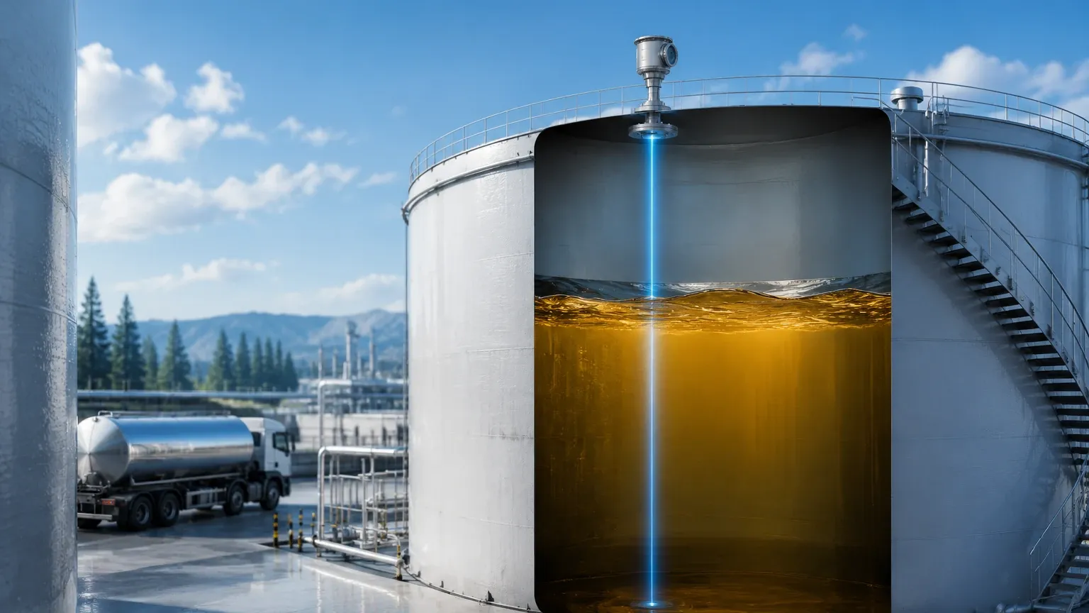
Radar technology uses electromagnetic waves. Frequency Modulated Continuous Wave (FMCW) radar, particularly at higher frequencies like 80 GHz, is increasingly the standard for diesel. Unlike sound, electromagnetic waves are unaffected by vapor, vacuum, or temperature changes. Given diesel's low dielectric constant, the radar must be sensitive enough to detect a weak reflection from the fuel surface. Modern 80 GHz radar units offer narrow beam angles, which are ideal for avoiding internal tank obstructions like baffles or heating coils.
4. Magnetic Level Gauges
This is a mechanical-visual method. A float containing a permanent magnet moves with the fuel level inside a bypass chamber or directly in the tank. This magnet flips external colored flaps (flags) to provide a highly visible local indication without requiring a power source. For remote monitoring, a reed chain transmitter or a magnetostrictive probe can be attached to the exterior of the gauge.
Technical Selection Criteria for Diesel Applications
Choosing a level indicator for diesel tank use involves more than just selecting a technology; it requires matching the sensor to the tank architecture and environmental conditions.
* Tank Geometry: Horizontal cylindrical tanks require different linearization than vertical tanks to convert level (mm) into volume (liters). Many modern transmitters include built-in strapping tables for this purpose.
* Hazardous Area Certification: Diesel is a combustible liquid. Depending on the local jurisdiction and the proximity to the tank vent, sensors usually require ATEX, IECEx, or UL certifications for Class I, Div 1 or 2 environments.
* Accuracy Requirements: For simple inventory (knowing when to refill), an accuracy of ±10 mm may suffice. For custody transfer or high-precision fuel management, ±1 mm or ±3 mm accuracy is often required.
* Mounting Constraints: Small tanks may only have 1-inch or 2-inch NPT/BSP openings, which may limit the use of certain radar antennas or large floats.
Comparison of Diesel Level Measurement Technologies
| Technology | Accuracy | Contact Type | Max Range | Key Advantage | Limitation |
| :— | :— | :— | :— | :— | :— |
| Radar (80 GHz) | ±1 mm | Non-contact | Up to 30m+ | Unaffected by vapor/temp | Higher initial cost |
| Ultrasonic | ±0.25% FS | Non-contact | 10m – 15m | Cost-effective | Sensitive to vapor/foam |
| Hydrostatic | ±0.1% to 0.5% | Contact | Unlimited | Easy to install in deep tanks | Density dependent |
| Magnetic Gauge | ±5 mm to 10 mm | Contact | 6m (standard) | Visual check without power | Moving parts can wear |
| Magnetostrictive| ±1 mm | Contact | 6m | High precision for fuel | Requires clean fluid |
Installation Considerations and Best Practices
To ensure the longevity and accuracy of a level indicator for diesel tank systems, specific installation protocols must be followed:
1. Venting and Pressure: Diesel tanks are usually vented to the atmosphere. However, during high-speed filling, internal pressure can fluctuate. Ensure that hydrostatic sensors are vented to the atmosphere via a capillary tube in the cable to compensate for barometric pressure changes.
2. The "Dead Zone" (Blocking Distance): All top-mounted non-contact sensors (radar and ultrasonic) have a minimum distance near the sensor face where measurement is impossible. If a tank is frequently filled to the brim, a nozzle extension or a different technology may be required to avoid entering this zone.
3. Stilling Wells: In tanks with significant turbulence or internal structures, installing the sensor inside a stilling well (a vertical pipe) can stabilize the liquid surface and provide a stronger signal return for radar or ultrasonic waves.
4. Grounding: Proper grounding of the instrument is essential to prevent static discharge, especially in fuel environments. This also protects the electronics from localized electrical interference.
Limitations of Common Technologies
While the technologies mentioned are robust, they are not without limitations. Hydrostatic sensors can be affected by the buildup of sludge or paraffin at the bottom of a diesel tank if they are not cleaned periodically. Ultrasonic sensors may struggle in very tall, narrow tanks due to signal interference from the walls (multipath reflections). Radar, while highly versatile, requires careful configuration when measuring media with low dielectric constants like diesel to ensure the signal-to-noise ratio remains high enough for reliable tracking.
For a comprehensive overview of available technologies and technical support for specific industrial configurations, you can review product options and application support on the Main Page.
Frequently Asked Questions (FAQ)
Q: Can I use a water level sensor for a diesel tank?
A: Not directly without adjustments. If using a hydrostatic sensor, it must be calibrated for the density of diesel (~0.85) rather than water (1.0). Furthermore, the materials (seals and cables) must be chemically compatible with hydrocarbons. Standard PVC cables will degrade in diesel; FEP or PUR cables are preferred.
Q: How does temperature affect diesel level readings?
A: Diesel expands as temperature increases. A volume-based measurement (like a float or radar) will show a higher level when the fuel is warm, even if the mass remains the same. Hydrostatic sensors measure the weight/mass, so they are less affected by thermal expansion but still require compensation for the electronics.
Q: Is non-contact measurement always better for diesel?
A: Non-contact (radar/ultrasonic) is often preferred because it reduces maintenance and avoids corrosion of moving parts. However, for small, mobile diesel tanks or those in high-vibration environments, a rugged hydrostatic or magnetic gauge might be more reliable and cost-effective.
Q: What is the maintenance schedule for a diesel level indicator?
A: For non-contact sensors, an annual visual inspection of the antenna/transducer face is usually sufficient. For contact-based systems like hydrostatic sensors or magnetic floats, semi-annual cleaning is recommended to prevent the accumulation of fuel sediment or microbial growth (often called "diesel bug") that can interfere with the sensor's movement or pressure ports.
Conclusion for Engineering Specifications
When specifying a level indicator for diesel tank applications, the priority should be placed on safety certifications and the stability of the measurement under varying environmental conditions. For critical infrastructure, such as data center backup generators, redundant systems—combining a non-contact radar for precision with a mechanical magnetic gauge for local backup—provide the highest level of reliability. By understanding the dielectric and density properties of diesel, engineers can select an instrument that minimizes maintenance while maximizing inventory accuracy. For more detailed technical specifications and model selections, visit the Main Page to consult with application specialists.