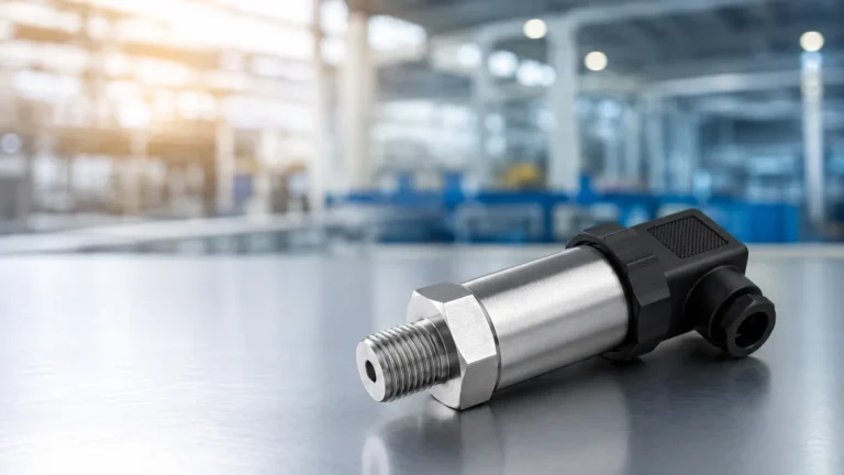
Vortex Shedding Flow Meter
Vortex Shedding Flow Meter
In the landscape of industrial process control, the vortex shedding flow meter has established itself as one of the most versatile and reliable instruments for measuring the flow rate of liquids, gases, and steam. Unlike mechanical meters that rely on moving parts susceptible to wear, the vortex meter utilizes the fluid dynamics principle known as the von Kármán effect. This article provides a comprehensive engineering reference for understanding, selecting, and installing vortex shedding flow meters in diverse industrial environments.
Understanding the Measurement Principle
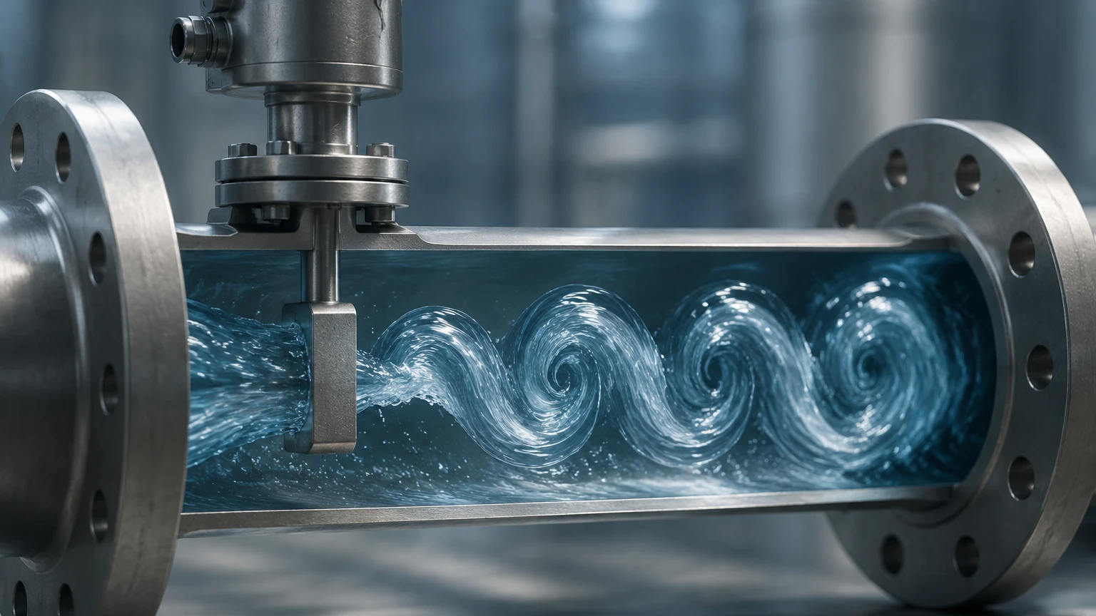
The operation of a vortex shedding flow meter is based on the physical phenomenon of vortex shedding. When a fluid—whether liquid, gas, or steam—encounters an obstruction in its path, it must move around that object. In a vortex meter, this obstruction is a non-streamlined object referred to as a "bluff body" or "shedder bar."
The von Kármán Effect
As the fluid flows past the bluff body, it cannot follow the sharp contours of the object. This causes the fluid layers to separate and form alternating vortices (swirls) on downstream sides of the body. These vortices are shed in a staggered, periodic pattern known as a von Kármán vortex street.
The fundamental principle is that the frequency ($f$) at which these vortices are shed is directly proportional to the velocity ($V$) of the fluid moving through the pipe. This relationship is defined by the Strouhal number ($St$), a dimensionless parameter that remains constant over a wide range of Reynolds numbers. The formula is expressed as:
$$f = St \times (V / d)$$
Where:
* $f$: Vortex shedding frequency
* $St$: Strouhal number (specific to the bluff body shape)
* $V$: Fluid velocity
* $d$: Width of the bluff body
Because the width of the bluff body and the cross-sectional area of the pipe are fixed, the meter can accurately calculate the volumetric flow rate by measuring the frequency of the pressure pulses generated by the shedding vortices.
Sensing the Vortices
To convert these physical vortices into a readable signal, the meter incorporates a sensor—typically a piezoelectric crystal or an ultrasonic sensor—located behind or within the bluff body. As each vortex passes, it creates a small localized pressure fluctuation. The sensor detects these fluctuations and transmits a frequency signal to the electronics (transmitter), which then scales the signal into a standard output such as 4-20mA, pulse, or a digital protocol like HART or Modbus.
Key Components and Construction
A standard vortex shedding flow meter consists of three primary elements:
1. The Meter Body: Usually constructed from stainless steel (e.g., 316 SS) or carbon steel, the body is designed to withstand the process pressure and temperature. It is available in wafer-style (clamped between flanges) or flanged versions.
2. The Bluff Body: This is the heart of the meter. Its geometry is precision-engineered to ensure stable vortex shedding across a broad flow range. A well-designed bluff body minimizes permanent pressure loss while maximizing signal strength.
3. The Transmitter: This unit houses the electronics that process the sensor signal. Modern transmitters often include temperature and pressure compensation (multivariable vortex meters) to provide mass flow readings, particularly useful for saturated and superheated steam applications.
For engineers looking to integrate these instruments into broader process control systems, including those requiring advanced Main Page solutions for tank and vessel management, understanding the synergy between flow and level measurement is essential for accurate mass balance.
Application Suitability and Selection Criteria
Vortex shedding flow meters are highly valued for their ability to handle high temperatures and pressures. They are particularly dominant in steam applications where other technologies, such as ultrasonic or electromagnetic meters, may fail or provide inaccurate data.
Selection Table: Fluid Compatibility
| Fluid Type | Suitability | Considerations |
| :— | :— | :— |
| Saturated Steam | Excellent | Ideal for energy management and boiler control. |
| Superheated Steam | Excellent | Requires pressure/temperature compensation for mass flow. |
| Clean Liquids | Good | Fluid must have low viscosity (< 30 cP). |
| Gases (Air, N2, etc.) | Excellent | High accuracy over a wide turndown ratio. |
| Cryogenic Fluids | Good | Requires specialized construction for extreme cold. |
| Slurries/High Viscosity | Poor | Not recommended; particles can damage the bluff body or clog sensors. |
| Corrosive Chemicals | Variable | Depends on the availability of compatible wetted materials. |
Key Evaluation Criteria
When selecting a vortex shedding flow meter, engineers must confirm several parameters to ensure long-term performance:
* Reynolds Number: The meter requires a minimum Reynolds number (typically > 10,000 to 20,000) to maintain a linear relationship between frequency and flow. Below this threshold, the vortex shedding becomes irregular.
* Process Temperature and Pressure: Standard models often handle up to 250°C (482°F), but high-temperature versions can reach 400°C (752°F). Ensure the flange rating matches the maximum process pressure.
* Turndown Ratio: Vortex meters typically offer a 10:1 to 30:1 turndown ratio. However, the "low-flow cutoff" is a critical limitation; if the velocity is too low, the vortices are too weak to be detected.
* Material Compatibility: Ensure the wetted parts are compatible with the process medium to prevent corrosion or erosion of the bluff body.
Installation Best Practices
Proper installation is the most significant factor in the accuracy of a vortex shedding flow meter. Because the meter relies on a stable flow profile to generate consistent vortices, any turbulence upstream can lead to measurement errors.
Straight Pipe Requirements
Standard installations require a specific length of straight pipe upstream and downstream of the meter. While requirements vary by manufacturer, a general guideline is:
* Upstream: 10 to 40 diameters (D), depending on the presence of elbows, valves, or reducers.
* Downstream: 5 diameters (D) to minimize back-pressure effects.
If the required straight runs are unavailable, flow straighteners or conditioners may be installed to normalize the flow profile.
Orientation and Piping
* Horizontal vs. Vertical: Vortex meters can be installed in horizontal or vertical lines. For liquid applications in vertical lines, the flow must be upward to ensure the pipe remains full. For steam or gas, orientation is less critical, though the transmitter should be positioned to avoid heat damage from the pipe.
* Vibration: Excessive pipe vibration can interfere with the piezoelectric sensors, as they may interpret vibration as vortex pulses. Use pipe supports on both sides of the meter to mitigate this risk.
* Avoid Cavitation: In liquid applications, the pressure drop across the bluff body can cause cavitation if the line pressure is too low. Ensure the downstream pressure is high enough to keep the fluid in a liquid state.
Advantages and Limitations
Advantages
* No Moving Parts: This translates to high reliability, low maintenance, and a long service life compared to turbine or positive displacement meters.
* Versatility: One meter design can often be used for liquid, gas, and steam with minimal configuration changes.
* Low Pressure Drop: The bluff body causes a relatively small permanent pressure loss compared to orifice plates.
* High Accuracy: Typically ±0.5% to ±1% of rate for liquids and ±1% to ±1.5% for gases and steam.
Limitations
* Low Flow Sensitivity: At low velocities, the vortex signal disappears, meaning the meter cannot measure flow down to zero.
* Viscosity Constraints: Highly viscous fluids dampen vortex formation. Generally, viscosity should be below 30 centipoise (cP).
* Vibration Sensitivity: While modern digital signal processing (DSP) helps, extreme mechanical vibration can still affect readings.
Frequently Asked Questions (FAQs)
Q: Can a vortex shedding flow meter measure multi-phase flow?
A: No. Vortex meters are designed for single-phase fluids. The presence of significant amounts of liquid in a gas stream (or gas bubbles in a liquid stream) will disrupt the vortex shedding pattern and cause significant errors.
Q: How does a vortex meter handle changing fluid density?
A: A standard vortex meter measures volumetric flow. To obtain mass flow for gases or steam, the density must be known. This is achieved either by inputting a fixed density into the transmitter or by using a multivariable vortex meter that measures temperature and pressure in real-time to calculate dynamic density.
Q: What maintenance is required for these meters?
A: Because there are no moving parts, maintenance is minimal. Periodic inspections should check for buildup on the bluff body or erosion of its edges, both of which can change the Strouhal number and affect accuracy.
Q: Is there a minimum velocity required for operation?
A: Yes. For most liquids, the minimum velocity is approximately 0.3 m/s (1 fps). For gases and steam, the minimum velocity depends on the fluid density but is generally around 3 to 6 m/s (10 to 20 fps).
Conclusion
The vortex shedding flow meter remains a cornerstone of industrial flow measurement due to its robust design and lack of mechanical wear. By understanding the underlying von Kármán effect and adhering to strict installation guidelines—particularly regarding straight pipe runs and vibration control—engineers can achieve highly accurate and repeatable measurements in even the most demanding steam and gas applications. When integrated with other process instruments, such as the level measurement solutions found on the Main Page, these meters contribute to a comprehensive and efficient industrial automation strategy.