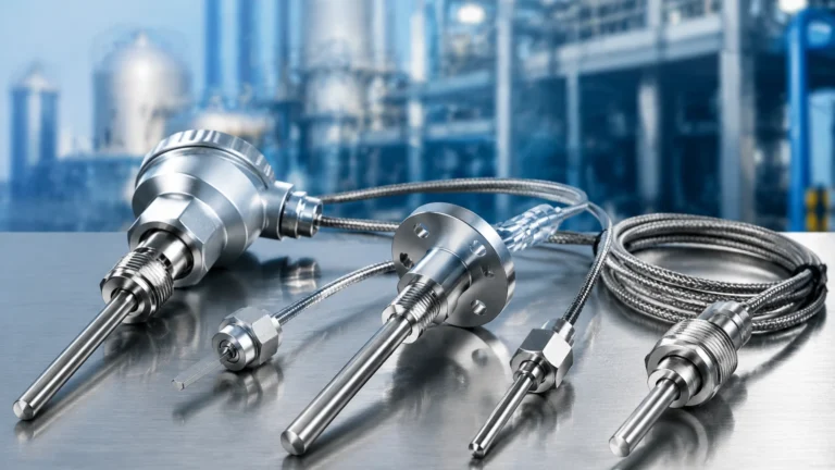
Water Oxygen Sensor
Water Oxygen Sensor
In industrial water treatment, aquaculture, and chemical processing, monitoring dissolved oxygen (DO) is critical for maintaining process efficiency and biological health. A water oxygen sensor is a precision instrument designed to measure the amount of gaseous oxygen (O2) dissolved in a liquid. Unlike gaseous oxygen measurement, dissolved oxygen is typically measured in milligrams per liter (mg/L), parts per million (ppm), or percentage of saturation.
For engineers and plant operators, selecting the correct water oxygen sensor requires an understanding of the underlying measurement physics, the environmental conditions of the application, and the integration requirements with other process instruments. While level measurement—such as the solutions provided on the Welk Main Page—manages the volume and inventory of liquids, oxygen sensors manage the chemical viability of the medium.
Measurement Principles of Water Oxygen Sensors
There are three primary technologies used to measure dissolved oxygen in industrial environments: polarographic, galvanic, and optical (fluorescence). Each has distinct operational characteristics and maintenance requirements.
1. Polarographic (Amperometric) Sensors
Polarographic sensors, often referred to as Clark electrodes, utilize a cathode (typically gold or platinum) and an anode (silver/silver chloride) submerged in an electrolyte solution, separated from the process water by a semi-permeable membrane.
* Principle: A constant polarizing voltage is applied to the electrodes. Oxygen molecules diffuse through the membrane and are reduced at the cathode, creating an electrical current. This current is directly proportional to the partial pressure of oxygen in the water.
* Characteristics: These sensors require a "warm-up" period to stabilize the polarizing voltage before measurement can begin. Because they consume oxygen during the measurement process, they require a constant flow of water (typically 0.3 m/s or higher) across the membrane to prevent localized oxygen depletion.
2. Galvanic Sensors
Galvanic sensors operate similarly to polarographic sensors but are self-polarizing.
* Principle: The electrode materials (typically a lead anode and a gold or silver cathode) have a sufficient difference in electrochemical potential to spontaneously reduce oxygen without an external power source.
* Characteristics: These sensors provide an immediate response upon power-up. Like polarographic sensors, they consume oxygen and require a minimum flow rate. The electrolyte and anode are eventually depleted, necessitating periodic replacement of the sensor cap or electrolyte.
3. Optical (Luminescence) Sensors
Optical water oxygen sensors represent the modern standard for many industrial applications due to their stability and low maintenance.
* Principle: The sensor uses a luminophore-coated sensing element. A blue light source (LED) excites the luminophore, which then emits red light. If oxygen molecules are present, they "quench" the luminescence. The sensor measures the phase shift or the decay time of the returned light, which is inversely proportional to the oxygen concentration.
* Characteristics: Optical sensors do not consume oxygen, meaning they can measure in stagnant water (zero flow). They are highly resistant to "poisoning" by gases like hydrogen sulfide (H2S), which can degrade electrochemical sensors.
Key Evaluation Criteria for Selection
When specifying a water oxygen sensor for an industrial project, the following technical factors must be evaluated to ensure long-term accuracy and reliability.
Temperature and Pressure Compensation
The solubility of oxygen in water is governed by Henry’s Law, which states that the amount of dissolved gas is proportional to its partial pressure above the liquid. However, this relationship is heavily influenced by temperature and atmospheric pressure.
* Temperature: As temperature increases, the solubility of oxygen decreases. Most industrial sensors include an integrated thermistor (PT100 or PT1000) to provide automatic temperature compensation (ATC).
* Pressure: Changes in barometric pressure or hydrostatic head (depth) affect the partial pressure of oxygen. High-end transmitters allow for manual or automated pressure compensation to maintain accuracy in deep tanks or high-altitude locations.
* Salinity: In aquaculture or seawater applications, dissolved salts reduce oxygen solubility. Sensors used in these environments must account for salinity correction factors.
Response Time (T90)
The T90 value indicates the time it takes for a sensor to reach 90% of the final reading after a step change in oxygen concentration. Optical sensors typically have a T90 of 30 to 60 seconds, while thin-membrane electrochemical sensors may respond faster but are more fragile.
Maintenance Interval
Electrochemical sensors require membrane replacement and electrolyte refilling every 3 to 6 months, depending on the severity of the application. Optical sensors generally only require a sensing cap replacement every 12 to 24 months.
Comparison Table: Water Oxygen Sensor Technologies
| Feature | Polarographic | Galvanic | Optical (LDO) |
| :— | :— | :— | :— |
| Oxygen Consumption | Yes | Yes | No |
| Minimum Flow Rate | >0.3 m/s | >0.3 m/s | 0 m/s (None) |
| Warm-up Time | 5–20 minutes | Instant | Instant |
| Maintenance Frequency | High (Electrolyte/Membrane) | High (Electrolyte/Anode) | Low (Annual Cap) |
| H2S Resistance | Poor | Poor | Excellent |
| Initial Cost | Moderate | Moderate | High |
| Long-term Stability | Moderate | Moderate | Excellent |
Installation Considerations and Best Practices
Proper installation is as important as sensor selection. Poor placement can lead to air bubble interference or inaccurate readings due to stagnant zones.
1. Mounting Angle: Sensors should be installed at an angle (typically 45 degrees) rather than perfectly vertical. This prevents air bubbles from becoming trapped on the sensing membrane or cap, which would cause artificially high oxygen readings.
2. Flow Orientation: For electrochemical sensors, the membrane must face into the flow of the liquid to ensure a continuous supply of fresh sample. In aeration basins, sensors should be placed in areas of representative mixing, away from the immediate vicinity of air diffusers.
3. Submersion Depth: Ensure the sensor is submerged deep enough to avoid surface turbulence but remains accessible for maintenance. For deep tank applications, specialized mounting hardware with cleaning ports is recommended.
4. Cable Management: Since DO sensors output low-level signals (in the case of analog versions) or digital protocols (Modbus RTU/RS485), cables should be shielded and routed away from high-voltage power lines to prevent electromagnetic interference (EMI).
Industrial Application Scenarios
Wastewater Treatment (Aeration Control)
In activated sludge processes, microorganisms require oxygen to break down organic matter. Aeration blowers are among the largest energy consumers in a treatment plant. By using a water oxygen sensor to provide real-time feedback, the plant can maintain DO levels between 1.5 and 2.0 mg/L, optimizing bacterial activity while significantly reducing energy costs.
Aquaculture and Fish Farming
Fish health is directly tied to dissolved oxygen levels. Sudden drops in DO can lead to mass mortality. Sensors in these environments must be robust enough to handle biofouling and are often integrated into automated aeration systems that trigger when DO levels fall below a specific threshold (e.g., 5 mg/L).
Boiler Feed Water
In high-pressure steam systems, even trace amounts of oxygen can cause severe pitting and corrosion in boilers and piping. Here, specialized "trace-level" DO sensors are used to measure oxygen in parts per billion (ppb) ranges, ensuring that oxygen scavengers are working effectively.

Limitations and Common Risks
While highly effective, water oxygen sensors are subject to several environmental limitations:
* Biofouling: In nutrient-rich water, algae and bacteria can grow on the sensor tip. This creates a localized micro-environment where oxygen levels differ from the bulk liquid. Automatic cleaning systems (air blast or mechanical wipers) are often necessary.
* Chemical Interference: Strong oxidants or reducing agents in the water can interfere with the redox reactions in electrochemical sensors. In such cases, optical sensors are the preferred alternative.
* Membrane Damage: In abrasive environments (e.g., slurries), suspended solids can tear the thin membranes of polarographic or galvanic sensors. Protective shrouds or optical sensors with reinforced caps should be used.
Integration with Level Measurement Systems
In many industrial setups, liquid level and liquid quality are monitored simultaneously. For example, in a chemical storage tank or a fermentation vessel, knowing the volume of the liquid is as vital as knowing its oxygen saturation. Welk’s range of level meters—including radar and ultrasonic sensors—provides the necessary data to manage tank volumes, while the water oxygen sensor ensures the process remains within chemical specifications.
Integrating both into a unified PLC or SCADA system allows for advanced process logic, such as adjusting aeration intensity based on the volume of liquid currently in a basin, a strategy that maximizes both chemical and energy efficiency.
Frequently Asked Questions (FAQs)
Q: How often should I calibrate my water oxygen sensor?
A: For most industrial applications, a calibration check every 2 to 4 weeks is recommended. Optical sensors are more stable and may only require calibration every 3 months. The most common method is "water-saturated air" calibration, where the sensor is held in 100% humidity air.
Q: Can I use a water oxygen sensor in saltwater?
A: Yes, but you must apply a salinity correction. Salt reduces the solubility of oxygen. Most modern transmitters have a setting to input the salinity (in ppt or mS/cm) to automatically adjust the mg/L reading.
Q: What is the difference between % Saturation and mg/L?
A: % Saturation measures the partial pressure of oxygen relative to the maximum amount of oxygen that could be dissolved in that water at that specific temperature and pressure. mg/L (or ppm) measures the actual mass of oxygen dissolved in a specific volume of water.
Q: Why is my sensor reading higher than expected in an aeration tank?
A: This is often caused by air bubbles collecting on the sensor membrane. Check the mounting angle and ensure the sensor is not placed directly above an air diffuser.
Conclusion and Technical Confirmation
Before proceeding with the procurement of a water oxygen sensor, project engineers should confirm the following data points:
1. Expected DO Range: Are you measuring in the ppm (standard) or ppb (trace) range?
2. Flow Conditions: Is the water moving, or is it stagnant?
3. Water Chemistry: Are there interfering gases (H2S) or high salinity levels?
4. Integration Requirements: Does the sensor need to output 4-20mA, Modbus, or HART protocol?
By aligning these parameters with the appropriate sensor technology—and ensuring robust level monitoring via the Main Page for overall tank management—operators can achieve precise control over their liquid processes, ensuring both safety and operational excellence.