Wastewater Measurement
Wastewater Measurement
Effective wastewater measurement is a cornerstone of modern industrial and municipal infrastructure. It ensures regulatory compliance, protects downstream environments, and optimizes the chemical and energy costs associated with treatment processes. Unlike clean water applications, wastewater presents unique challenges including the presence of suspended solids, corrosive gases, fluctuating temperatures, and surface foam. Selecting the appropriate instrumentation requires a deep understanding of the physical principles governing different sensor technologies and the specific demands of the wastewater environment.
In the context of process automation, wastewater measurement typically refers to the monitoring of liquid levels in sumps, lift stations, aeration tanks, and open channels. This article provides a technical guide to selecting and implementing level measurement solutions tailored for these demanding conditions.
Core Principles of Level Measurement Technologies
Before selecting a device, engineers must understand the underlying physics of the most common measurement methods used in wastewater applications. Each technology interacts differently with the media and the surrounding environment.
Ultrasonic Level Measurement (Non-Contact)
Ultrasonic sensors operate on the "time-of-flight" principle. The sensor emits a high-frequency sound pulse that travels through the air, reflects off the liquid surface, and returns to the transducer. The distance is calculated based on the time interval and the speed of sound in air ($v \approx 343$ m/s at 20°C).
* Advantages: No contact with the corrosive wastewater, relatively low cost, and easy to install.
* Limitations: The speed of sound changes with air temperature, requiring integrated temperature compensation. Furthermore, heavy foam or steam can absorb or scatter the sound waves, leading to signal loss.
Radar Level Measurement (Non-Contact)
Radar sensors also use time-of-flight but employ electromagnetic waves (microwaves) rather than sound. Modern wastewater facilities increasingly favor 80 GHz high-frequency radar for its narrow beam angle and high precision.
* Advantages: Microwaves are unaffected by air temperature, pressure, or vacuum. They can penetrate light foam and are not influenced by vapors or dust. The narrow beam allows for installation in tight spaces or tanks with internal obstructions.
* Limitations: Higher initial capital expenditure compared to ultrasonic sensors, though lower maintenance often offsets this over the lifecycle.
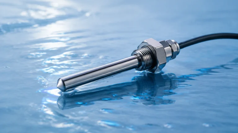
Hydrostatic Pressure Measurement (Contact)
This method measures the liquid level by sensing the pressure exerted by the liquid column above the sensor. The relationship is defined by the formula $P = \rho gh$, where $P$ is pressure, $\rho$ is the liquid density, $g$ is gravity, and $h$ is the height of the liquid.
* Advantages: Ideal for deep wells, lift stations, and areas where surface foam or turbulence makes non-contact measurement difficult.
* Limitations: The sensor is submerged, making it susceptible to fouling from grease, sludge, or debris. It also requires a vent tube in the cable to compensate for changes in atmospheric pressure.
For a detailed technical comparison of these instruments, engineers can consult the Main Page for specific product data sheets and performance curves.
Technology Selection for Specific Wastewater Applications
Not all wastewater measurement points are equal. The choice of technology must align with the specific hydraulic and chemical characteristics of the site.
Lift Stations and Wet Wells
Lift stations are characterized by high turbulence, the presence of grease/scum layers, and potentially explosive atmospheres (methane).
* Recommendation: Non-contact radar is the preferred choice to avoid fouling. If foam is excessive, a submersible hydrostatic transmitter with a large, flush diaphragm can be used to minimize clogging.
Aeration Tanks
In biological treatment, aeration tanks contain high levels of foam and bubbles created by blowers.
* Recommendation: Ultrasonic sensors often fail here due to signal absorption by the foam. Radar sensors, particularly those operating at higher frequencies, are more reliable. If the foam is extremely thick and dense, a guided wave radar (GWR) or a hydrostatic sensor may be necessary.
Open Channel Flow (Flumes and Weirs)
Inflow and outflow are often measured in open channels using primary devices like Parshall flumes. The level measurement is converted to a flow rate using standardized equations.
* Recommendation: Ultrasonic sensors are the industry standard for open channel flow due to their cost-effectiveness and ease of integration with flow totalizers. However, in outdoor installations where solar heating can create temperature gradients in the air space, radar provides superior stability.
Practical Selection Matrix
The following table provides a general guideline for technology selection based on common wastewater process conditions.
| Application Feature | Ultrasonic | Radar (80 GHz) | Hydrostatic | Magnetic Level Gauge |
| :— | :— | :— | :— | :— |
| Surface Foam | Poor (Signal loss) | Good (Penetrates light foam) | Excellent (Ignores foam) | N/A |
| Corrosive Vapors | Moderate (Requires PVDF) | Excellent (PTFE faces) | Good | Good |
| Heavy Turbulence | Moderate | Good | Excellent | Poor |
| Build-up/Debris | Excellent (Non-contact) | Excellent (Non-contact) | Poor (Requires cleaning) | Poor |
| Deep Wells (>15m) | Moderate | Excellent | Excellent | N/A |
| Cost | Low | Medium to High | Medium | High |
Installation Guidelines and Best Practices
Proper installation is as critical as technology selection. Even the most advanced sensor will provide inaccurate data if poorly positioned.
1. Avoid the "Dead Zone": Every non-contact sensor has a blocking distance (dead zone) near the transducer face where measurement is impossible. Ensure the sensor is mounted high enough that the maximum possible liquid level never enters this zone.
2. Beam Path Clearance: For ultrasonic and radar sensors, the "beam" spreads as it travels. Ensure there are no ladders, pipes, or pumps within the beam angle that could cause false echoes.
3. Mounting Position: Sensors should be mounted away from the inlet pipe to avoid the turbulence and aeration caused by falling water. Ideally, the sensor should be placed in a location representing the average surface level.
4. Stilling Wells: In extremely turbulent tanks, a stilling well (a vertical pipe) can be used to provide a calm surface for the sensor to measure. This is particularly useful for hydrostatic and guided wave radar sensors.
5. Submersible Venting: For hydrostatic sensors, ensure the moisture-protection bellows at the end of the vent tube are clear. A blocked vent tube will result in measurement errors whenever the barometric pressure changes.

Managing Risks: Environmental and Process Challenges
Wastewater measurement environments are inherently hostile. Engineers must account for the following risks during the design phase:
Chemical Compatibility
Wastewater can contain a variety of acids, bases, and hydrocarbons. For contact sensors (hydrostatic), the housing and cable material (e.g., PVC, PUR, or FEP) must be compatible with the effluent. For non-contact sensors, the transducer face is typically made of PVDF or PTFE to resist corrosion from hydrogen sulfide ($H_2S$) gas.
Condensation and Icing
In outdoor applications or humid tanks, condensation can form on the sensor face. While radar is generally more tolerant of this, some ultrasonic sensors feature a "self-cleaning" function through the vibration of the transducer. In cold climates, heated enclosures or specialized coatings may be required to prevent ice buildup.
Lightning and Surges
Since many wastewater measurement points are located in open areas or at the end of long cable runs, they are susceptible to lightning strikes. Using instruments with integrated surge protection and ensuring proper grounding of the shielded cable is essential for long-term reliability.
Technical FAQ
Q: How often should wastewater level sensors be calibrated?
A: For non-contact sensors in stable environments, an annual check is usually sufficient. Hydrostatic sensors in high-sludge environments may require quarterly cleaning and verification to account for sensor drift or fouling.
Q: Can radar measure through a plastic tank roof?
A: Yes, certain radar frequencies can penetrate plastic or fiberglass tank tops, allowing for measurement without cutting a hole in the vessel. This is useful for chemical storage tanks used in wastewater treatment.
Q: What is the impact of H2S gas on sensors?
A: Hydrogen sulfide is highly corrosive. It can permeate standard cable jackets and attack copper wiring. For wastewater measurement, always specify gas-tight sensors or materials like Viton and high-grade stainless steel (316L).
Q: Is 4-20mA or Modbus better for wastewater sites?
A: 4-20mA HART is the industry standard due to its simplicity and ability to power the loop. However, Modbus or PROFIBUS is advantageous for large-scale plants where multiple data points (level, temperature, diagnostics) need to be transmitted over a single pair of wires.
Verification Checklist for Project Planning
Before finalizing a wastewater measurement project, technical teams should confirm the following details:
* Media Composition: Are there high concentrations of fats, oils, and grease (FOG)?
* Tank Geometry: Are there internal obstructions like agitators or support beams?
* Measurement Range: What are the minimum and maximum levels (in meters)?
* Power Availability: Is there 24V DC loop power, or is local AC power required?
* Output Requirements: Is a simple analog signal sufficient, or is digital communication (HART/RS485) needed for remote diagnostics?
* Hazardous Area Rating: Does the installation site require ATEX or IECEx certification for explosive atmospheres?
By systematically addressing these criteria, facility managers can ensure that their wastewater measurement systems provide the accuracy and reliability necessary for modern process control.