Water Level Control
Water Level Control
In industrial process automation, water level control is a fundamental requirement for ensuring operational safety, efficiency, and resource management. Whether managing a municipal wastewater treatment plant, a high-pressure boiler system, or a chemical storage facility, the ability to monitor and regulate liquid levels precisely prevents equipment damage, reduces waste, and maintains consistent throughput. Effective control is not merely about measuring a height; it involves a coordinated loop of sensors, controllers, and actuators that respond to real-time process variables.
For engineers and facility managers, selecting the appropriate technology for water level control requires a deep understanding of the physical principles governing different measurement methods. This guide examines the primary technologies used in modern industry, their selection criteria, and the practical considerations for successful implementation.
Principles of Level Measurement
Before implementing a water level control system, it is essential to understand the physics behind the sensors. Industrial level measurement is generally categorized into non-contact and contact methods.
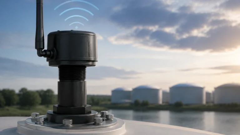
Radar Level Measurement (ToF)
Radar level meters utilize Time-of-Flight (ToF) technology. The sensor emits high-frequency microwave pulses (typically in the 26GHz or 80GHz range) that travel toward the water surface. When the pulses hit the surface, they are reflected back to the sensor. The device calculates the distance based on the time interval between emission and reception.
Radar is highly regarded for its accuracy and reliability because microwaves are largely unaffected by air temperature, pressure, or the presence of dust and steam. This makes radar an excellent choice for complex industrial environments where other sensors might fail.
Ultrasonic Level Measurement
Similar to radar, ultrasonic sensors use the ToF principle but rely on sound waves rather than electromagnetic waves. The transducer emits an ultrasonic pulse that reflects off the liquid surface. Because the speed of sound is affected by air temperature, these sensors typically include built-in temperature compensation.
Ultrasonic sensors are cost-effective and ideal for open-channel flow and standard atmospheric tanks. However, they are sensitive to heavy foam, which can absorb the sound signal, and vacuum conditions, where sound cannot travel.
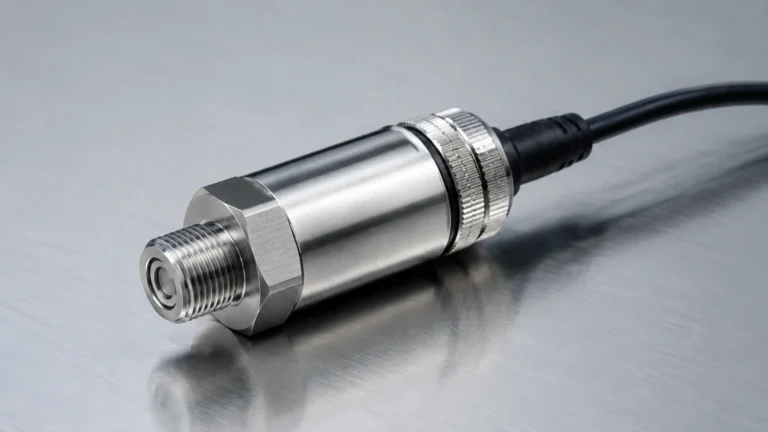
Hydrostatic Level Measurement
Hydrostatic transmitters measure the pressure exerted by the liquid column above the sensor. Based on the principle that pressure ($P$) equals density ($ρ$) multiplied by gravity ($g$) and height ($h$), the sensor converts the measured pressure into a level reading.
This method is highly effective for deep wells, boreholes, and large storage tanks. Submersible hydrostatic sensors are common in water level control for groundwater monitoring, provided the density of the water remains relatively constant.
Magnetic Level Gauges
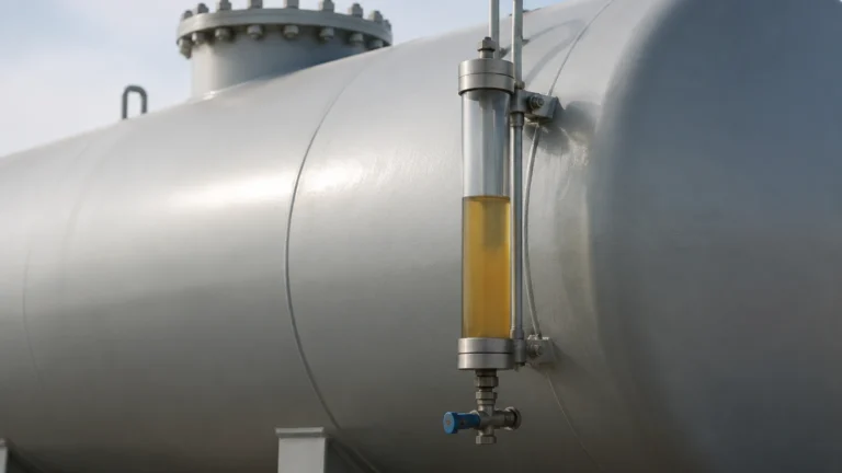
Magnetic level gauges utilize buoyancy and magnetic coupling. A float containing a permanent magnet moves with the water level inside a bypass chamber. Outside the chamber, a magnetic indicator (or a series of flaps) tracks the float's movement, providing a clear visual representation. By adding reed switches or a magnetostrictive transmitter, this mechanical system can be integrated into an automated control loop.
Technology Selection for Water Level Control
Choosing the right instrument depends on the specific demands of the application. The following table provides a comparison of the primary technologies used in industrial water level control.
| Feature | Radar Level Meters | Ultrasonic Sensors | Hydrostatic Transmitters | Magnetic Gauges |
| :— | :— | :— | :— | :— |
| Measurement Type | Non-contact | Non-contact | Contact (Pressure) | Contact (Buoyancy) |
| Accuracy | ±2 mm to ±5 mm | ±0.25% of range | ±0.1% to ±0.5% | ±5 mm to ±10 mm |
| Max Range | Up to 100 m | Up to 30 m | Up to 200 m | Up to 6 m |
| Process Temp. | -40°C to +450°C | -40°C to +80°C | -20°C to +85°C | Up to +400°C |
| Process Pressure | Vacuum to 160 bar | Atmospheric | Up to 40 bar | Up to 160 bar |
| Common Use | Chemical tanks, Steam | Water treatment, Sumps | Deep wells, Reservoirs | Boilers, Oil/Water |
Implementing the Control Loop
A functional water level control system consists of three main components:
1. The Sensor (Input): This is the primary element (e.g., a radar transmitter or level switch) that detects the current state of the water level.
2. The Controller (Logic): Typically a PLC (Programmable Logic Controller) or a dedicated level controller. It receives the 4-20mA or digital signal from the sensor and compares it against a predefined setpoint.
3. The Actuator (Output): This is the device that physically changes the level, such as a variable frequency drive (VFD) on a pump or a motorized control valve.
In a "Pump Down" application (common in sumps), the controller activates a pump when the water reaches a high-level setpoint and deactivates it once it hits a low-level setpoint. Conversely, in a "Fill" application (common in storage tanks), the logic is reversed to prevent the tank from running dry.
For more information on selecting specific instruments for these loops, you can visit the Main Page of Welk's technical catalog.
Installation Considerations and Best Practices
Even the most advanced sensor will fail to provide accurate water level control if installed incorrectly. Engineers must account for the following factors during the design phase:
Dead Zones (Blocking Distance)
Both radar and ultrasonic sensors have a "dead zone" or blocking distance immediately below the sensor face where measurement is impossible. For ultrasonic sensors, this is typically 0.25 m to 0.6 m. Ensure the maximum water level never enters this zone to avoid signal loss or false high readings.
Mounting and Positioning
* Avoid Obstructions: Sensors should be mounted away from inlet pipes, ladders, and agitators. These internal structures can create false echoes (parasitic reflections) that interfere with the true level signal.
* Perpendicular Alignment: For non-contact sensors, the transducer face must be perfectly perpendicular to the water surface. A slight tilt can cause the signal to reflect away from the receiver, leading to intermittent data.
* Stilling Wells: In applications with heavy turbulence or surface agitation, installing the sensor inside a stilling well (a vertical pipe) can provide a calm surface for more stable readings.
Environmental Protection
For hydrostatic sensors used in outdoor reservoirs, lightning protection and moisture-proof venting are critical. The capillary tube in the sensor cable must remain unobstructed to allow the sensor to compensate for changes in atmospheric pressure.
Limitations and Common Risks
While modern instrumentation is robust, certain conditions can compromise water level control accuracy:
* Foam and Turbulence: Thick foam can absorb ultrasonic waves, leading to "lost echo" errors. Radar is generally more resistant but may still require specific frequency adjustments (e.g., 80GHz) to penetrate light foam.
* Build-up and Scaling: In wastewater or chemical applications, material can build up on contact probes or the faces of ultrasonic transducers. Regular maintenance and the use of non-stick materials (like PTFE) are necessary to mitigate this.
* Density Variations: Hydrostatic measurement is dependent on liquid density. If the water temperature fluctuates significantly or if there are varying concentrations of dissolved solids, the pressure-to-level conversion will drift unless compensated by a secondary temperature sensor or manual calibration.
Frequently Asked Questions (FAQ)
Q: Can I use an ultrasonic sensor for boiling water?
A: It is generally not recommended. Steam and heavy vapor significantly change the speed of sound in the air space above the water, leading to large measurement errors. Radar is the preferred choice for high-vapor applications.
Q: How do I choose between a level switch and a level transmitter?
A: A level switch provides point-level detection (e.g., "Full" or "Empty") and is best for simple overfill protection. A level transmitter provides a continuous signal (e.g., 0% to 100%) and is necessary for precise water level control where you need to know the exact height at all times.
Q: What is the advantage of 80GHz radar over 26GHz radar?
A: 80GHz radar has a narrower beam angle, which allows it to avoid internal tank obstructions more easily and provides better performance on low-dielectric liquids or in small vessels.
Q: Is hydrostatic measurement suitable for pressurized tanks?
A: Only if you use a differential pressure (DP) transmitter. A standard submersible hydrostatic sensor cannot distinguish between the liquid head pressure and the overhead gas pressure in a sealed tank.
Conclusion
Effective water level control is the backbone of industrial fluid management. By understanding the measurement principles of radar, ultrasonic, and hydrostatic technologies, engineers can design systems that are both accurate and resilient. Proper installation, including the management of dead zones and the avoidance of internal obstructions, remains the most critical factor in long-term reliability. As industrial requirements become more stringent, the integration of high-precision sensors into automated control loops will continue to be a primary focus for operational excellence.