Water Level Sensor for Pump
Water Level Sensor for Pump
In industrial fluid management, the integration of a water level sensor for pump control is a fundamental requirement for operational safety and efficiency. Whether managing a municipal wastewater lift station, a chemical processing tank, or a cooling tower, the synergy between level measurement and pump actuation prevents catastrophic equipment failure and optimizes energy consumption. A well-chosen sensor ensures that pumps do not run dry—a leading cause of seal failure and motor burnout—and prevents tank overflows that result in environmental hazards and material loss.
Selecting the appropriate technology requires a deep understanding of measurement principles, fluid dynamics, and the specific demands of the pumping environment. This guide examines the primary technologies used in pump control, provides selection criteria, and outlines best practices for installation and maintenance.
Measurement Principles for Pump Control
Before selecting a water level sensor for pump applications, it is essential to understand the physical principles governing different measurement technologies. Each method has distinct advantages depending on the fluid properties and the physical constraints of the installation.
Hydrostatic Pressure Measurement
Hydrostatic level transmitters operate on the principle that the pressure at the bottom of a liquid column is directly proportional to the height of the liquid above it. The relationship is defined by the formula $P = \rho gh$, where $P$ is pressure, $\rho$ (rho) is the liquid density, $g$ is the gravitational constant, and $h$ is the height of the liquid.
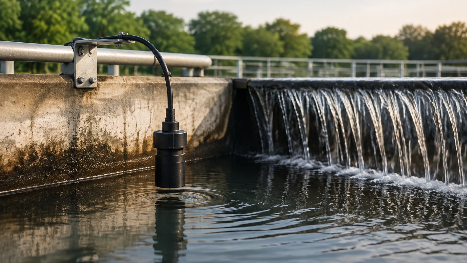
In pump applications, these sensors are often submersible. A stainless steel diaphragm senses the pressure, and a vented cable compensates for atmospheric pressure changes. This technology is highly effective for deep wells and large reservoirs where top-down access is limited.
Ultrasonic (Non-Contact) Measurement
Ultrasonic sensors emit high-frequency sound pulses that travel through the air, reflect off the liquid surface, and return to the transducer. The sensor measures the "time-of-flight" to calculate the distance. Because these sensors do not touch the liquid, they are ideal for corrosive or dirty water that might damage contact-based probes. However, they are sensitive to foam, heavy steam, and extreme turbulence, which can scatter the sound waves.
Radar (FMCW and Pulse) Measurement
Radar level meters use high-frequency electromagnetic waves (microwaves) rather than sound. Frequency Modulated Continuous Wave (FMCW) radar is particularly effective for pump control in challenging environments. Unlike ultrasonic waves, radar signals are unaffected by air temperature fluctuations, vacuum, or high pressure. They can penetrate steam and dust, making them the preferred choice for industrial chemical tanks and high-temperature water applications.
Float and Magnetic Level Switches
For simple start/stop pump control, point-level switches remain a staple. A float switch uses a buoyant element containing a microswitch or a magnet that actuates a reed switch as the water level rises or falls. While they do not provide a continuous 4-20mA signal for precise level monitoring, they are highly reliable for secondary high-level alarms or basic sump pump automation.
Choosing the Right Water Level Sensor for Pump Applications
Selecting a water level sensor for pump systems involves more than just matching a budget. Engineers must evaluate the chemical compatibility, the physical layout of the tank or pit, and the required level of automation.
1. Fluid Characteristics
If the water contains high levels of solids, grease, or corrosive chemicals (as seen in wastewater or chemical dosing), non-contact sensors like ultrasonic or radar are generally preferred to reduce maintenance. For clean water in deep boreholes, a submersible hydrostatic transmitter is often the most cost-effective and accurate solution.
2. Tank Geometry and Obstructions
Internal structures such as ladders, agitators, or the pump housing itself can interfere with the signal of non-contact sensors. Radar sensors with narrow beam angles can often be programmed to ignore these obstructions, whereas ultrasonic sensors might require a stilling well to provide a stable reading in turbulent conditions.
3. Control Requirements
Do you need a simple "on/off" trigger, or do you need to modulate pump speed via a Variable Frequency Drive (VFD)?
* Point Level: Best for simple overflow or dry-run protection.
* Continuous Level: Necessary for VFD integration, allowing the pump to slow down as the target level is approached, which reduces water hammer and extends pump life.
For a comprehensive look at available technologies and technical specifications, engineers should Review product options and application support to ensure the hardware matches the specific process demands.
Practical Selection Table
| Technology | Best Use Case | Max Range (Typical) | Pros | Cons |
| :— | :— | :— | :— | :— |
| Hydrostatic | Deep wells, vented tanks | 0–200m (656 ft) | Accurate, easy to install in deep pits | Sensitive to density changes |
| Ultrasonic | Wastewater, open channels | 0–15m (49 ft) | Non-contact, low maintenance | Affected by foam and steam |
| Radar | Chemical tanks, high temp | 0–30m+ (98 ft+) | Highly precise, ignores vapor | Higher initial cost |
| Float Switch | Sump pumps, high alarms | N/A (Point) | Very low cost, simple | Moving parts can foul |
Installation and Integration Guidelines
Proper installation is as critical as sensor selection. Even the most advanced water level sensor for pump control will fail if it is positioned incorrectly.
Avoiding Turbulence and Inflow
Sensors should never be installed directly under an inflow pipe. The turbulence and aeration caused by falling water will create "noise" for ultrasonic and radar sensors and can cause physical instability for hydrostatic probes. If the tank is highly turbulent due to pump action, a stilling well (a vertical pipe with vent holes) should be used to provide a calm surface for measurement.
The "Dead Zone" or Blocking Distance
Ultrasonic and radar sensors have a minimum detection distance, often called the "dead zone." If the water level rises into this zone, the sensor will lose its signal or provide an erroneous reading. Ensure the sensor is mounted high enough so that the maximum possible water level never enters this area.
Wiring and Signal Integrity
In industrial environments, electromagnetic interference (EMI) from large pump motors can degrade the signal from a level sensor. Use shielded twisted-pair cabling and ensure the sensor is properly grounded. For long-distance transmissions (e.g., from a remote reservoir to a control room), a 4-20mA current loop is the industry standard due to its resistance to signal loss.
Limitations and Common Risks
While modern sensors are highly reliable, they are not infallible. Understanding their limitations is key to building a resilient system.
* Sensor Fouling: In wastewater applications, fats, oils, and grease (FOG) can build up on hydrostatic diaphragms or ultrasonic transducers. Regular inspection and cleaning cycles must be established.
* Specific Gravity Changes: Hydrostatic sensors assume a constant fluid density. If the pump is moving brine or chemical-heavy water where the density fluctuates, the level reading will drift unless compensated for by the control system.
* Dry Run Protection Redundancy: For critical high-value pumps, it is a best practice to use a continuous level sensor for primary control and a separate mechanical float switch for redundant dry-run protection. This ensures that if the primary sensor fails or the PLC freezes, the pump is still protected by a hard-wired safety circuit.
Frequently Asked Questions
Q: Can I use an ultrasonic sensor in a pressurized tank?
A: Generally, no. Ultrasonic sensors rely on the speed of sound, which changes with air density and pressure. Radar is the preferred non-contact technology for pressurized vessels.
Q: How do I calibrate a hydrostatic level sensor for a specific liquid?
A: Most modern transmitters from manufacturers like Welk allow for field calibration. You must input the specific gravity of the liquid into the transmitter or the receiving controller to ensure the pressure-to-level conversion is accurate.
Q: What is the benefit of a 4-20mA signal over a 0-10V signal?
A: A 4-20mA signal is a current loop, which is much less susceptible to voltage drops over long cable runs and is more resistant to electrical noise from pump motors. Additionally, a 4mA floor allows the system to detect a "wire break" (0mA), which a 0-10V system cannot easily distinguish from a zero-level reading.
Q: Is radar overkill for simple water tank pump control?
A: It depends on the environment. If the tank is outdoors and subject to temperature extremes or if there is significant condensation, a 26GHz or 80GHz radar will be much more reliable than ultrasonic, potentially saving more in maintenance costs than the initial price difference.
Conclusion
Implementing a reliable water level sensor for pump automation is a balance of physics, environment, and budget. By understanding the measurement principles of hydrostatic, ultrasonic, and radar technologies, engineers can select a solution that minimizes maintenance and maximizes pump lifespan. For those looking to upgrade their current systems or design new installations, Welk provides a range of industrial-grade instruments designed for the rigors of modern process automation. Always verify the specific chemical compatibility and environmental ratings of your chosen sensor before finalizing the system design to ensure long-term operational success.