Water Measurement Devices
Water Measurement Devices
In industrial process control and environmental management, the accurate monitoring of liquid levels is a fundamental requirement. Water measurement devices encompass a broad range of technologies designed to quantify the volume, height, or presence of water within tanks, reservoirs, open channels, and deep wells. Selecting the appropriate technology requires a deep understanding of the physical principles governing each sensor type, as well as the specific environmental constraints of the application.
For engineers and facility managers, the goal is to balance precision, reliability, and cost-effectiveness. Whether managing a municipal wastewater treatment plant or a high-pressure boiler system in a chemical facility, the choice of instrumentation directly impacts operational safety and efficiency. This guide explores the primary technologies used in modern industrial level measurement, providing the technical foundation necessary for informed equipment selection.
Understanding the Core Technologies of Water Measurement Devices
Water measurement devices are generally categorized by their method of interaction with the medium: non-contact and contact-based. Non-contact methods are often preferred for corrosive or high-purity liquids where contamination or sensor degradation must be avoided. Contact-based methods are frequently utilized in deep-well monitoring or applications where physical constraints prevent a clear line of sight from the top of a vessel.
Non-Contact Measurement: Radar and Ultrasonic Sensors
Radar Level Measurement (FMCW and Pulse)
Radar level meters operate on the principle of electromagnetic wave reflection. The device emits a high-frequency signal (typically in the 26GHz or 80GHz range) toward the water surface. When the signal hits the water, which has a relatively high dielectric constant ($\\varepsilon_r \\approx 80$), a significant portion of the energy is reflected back to the sensor.
* Principle: The sensor measures the time-of-flight (ToF) or the frequency shift (in Frequency Modulated Continuous Wave radar) between the emitted and received signals to calculate the distance to the surface.
* Advantages: Radar is unaffected by air temperature, pressure, or vacuum conditions. It can penetrate steam and dust, making it ideal for harsh industrial environments.
* Limitations: While highly versatile, radar sensors can be more expensive than ultrasonic alternatives and may require specific mounting to avoid internal tank obstructions.
Ultrasonic Level Measurement
Ultrasonic water measurement devices utilize sound waves rather than electromagnetic waves. The sensor emits a pulse of mechanical energy at a frequency above the human hearing range (typically 20kHz to 50kHz).
* Principle: The device measures the time it takes for the sound pulse to travel to the water surface and return. Since the speed of sound in air is approximately 343 m/s (at 20°C), the distance can be calculated accurately.
* Advantages: Ultrasonic sensors are cost-effective and easy to install. They are widely used in open-channel flow measurement and irrigation systems.
* Limitations: The speed of sound varies with air temperature; therefore, these sensors must include integrated temperature compensation. They are also sensitive to heavy foam, which can absorb the sound pulse, and wind or steam, which can distort the signal.
Contact-Based Measurement: Hydrostatic and Magnetic Gauges
Hydrostatic Pressure Transmitters
Hydrostatic measurement is based on the physical law that the pressure at the bottom of a liquid column is proportional to the height of that column multiplied by the density of the liquid ($P = \\rho gh$).
* Principle: A pressure sensor is placed at the bottom of the tank or submerged in a well. It measures the "head pressure" exerted by the water above it.
* Advantages: This is the standard for deep-well and borehole monitoring. It is a robust technology that is not affected by surface turbulence or foam.
* Limitations: If the density of the liquid changes (e.g., due to significant temperature fluctuations or chemical additives), the level reading will drift unless compensated. Submersible versions also require a vented cable to account for changes in atmospheric pressure.
Magnetic Level Gauges
Magnetic level gauges provide both a visual indication and a signal output. They consist of a float containing a permanent magnet that moves within a bypass chamber connected to the vessel.
* Principle: As the water level rises or falls, the float moves accordingly. A series of bi-color magnetic flaps on the outside of the chamber flip to indicate the level, while an optional reed-chain transmitter can provide a 4-20mA signal for remote monitoring.
* Advantages: They provide a clear, power-free visual reading and are excellent for high-pressure and high-temperature applications.
* Limitations: They require physical space for the bypass chamber and are not suitable for liquids containing magnetic particles or high-viscosity fluids that might cause the float to stick.
Selection Criteria for Industrial Water Level Monitoring
Choosing between different water measurement devices involves evaluating the specific parameters of the installation site. For a comprehensive overview of available technologies and specific model specifications, you may review product options and application support on our Main Page.
| Feature | Radar (80GHz) | Ultrasonic | Hydrostatic | Magnetic Gauge |
| :— | :— | :— | :— | :— |
| Accuracy | ±1 mm to ±2 mm | ±0.25% of range | ±0.1% to ±0.5% | ±5 mm |
| Max Range | Up to 120m | Up to 30m | Up to 500m (depth) | Up to 6m (standard) |
| Media Type | All liquids | Clean water/liquids | All liquids | Clean/Non-viscous |
| Process Temp | -40°C to +250°C | -40°C to +80°C | -20°C to +80°C | Up to +450°C |
| Pressure | Vacuum to 160 bar | Atmospheric | Submersible/Process | Up to 320 bar |
Key Considerations for Selection:
1. Chemical Compatibility: Ensure the wetted parts (e.g., PTFE for radar antennas, stainless steel for hydrostatic diaphragms) are compatible with the water's chemical makeup, especially in wastewater or chemical dosing applications.
2. Tank Geometry: Internal structures like agitators, heating coils, or ladders can create false echoes for radar and ultrasonic sensors. Modern radar units often feature "false echo suppression" software to ignore these reflections.
3. Measurement Range: While ultrasonic sensors are excellent for short ranges (under 10 meters), long-range requirements in silos or deep reservoirs usually necessitate radar or hydrostatic transmitters.
4. Power Availability: In remote water management locations, low-power hydrostatic sensors or battery-operated ultrasonic units are often preferred to minimize energy consumption.
Installation Best Practices and Common Pitfalls
Correct installation is as critical as selecting the right technology. Even the most advanced water measurement devices will fail if environmental factors are ignored.
1. The "Dead Zone" or Blocking Distance
All top-mounted sensors (Radar and Ultrasonic) have a minimum distance below the sensor where they cannot accurately measure. This is known as the dead zone. If the water level rises into this zone, the sensor may output an error or a fixed maximum value. Always mount the sensor high enough to ensure the maximum water level never enters this region.
2. Avoiding Obstructions
For non-contact sensors, the signal beam spreads as it travels. The "beam angle" determines the diameter of the area the sensor sees. If the beam hits a wall or a pipe before it hits the water, it will return an inaccurate reading.
* Rule of thumb: Mount the sensor at least 200mm to 500mm away from the tank wall, depending on the beam angle and tank depth.
3. Turbulence and Inflow
Water measurement devices should never be installed directly above an inflow pipe. The turbulence and air bubbles created by the falling water will scatter ultrasonic and radar signals and create localized pressure spikes for hydrostatic sensors. If turbulence is unavoidable, a stilling well (a perforated pipe) should be used to provide a calm surface for measurement.
4. Atmospheric Venting
Hydrostatic pressure sensors measure the difference between the water pressure and the atmospheric pressure. For submersible sensors, this requires a vent tube inside the cable. If this tube is kinked or blocked, or if moisture enters the tube, the reading will become inaccurate. Desiccant cartridges are often used at the termination point to prevent moisture ingress.

Frequently Asked Questions (FAQs)
Q: Can ultrasonic sensors be used in vacuum tanks?
A: No. Ultrasonic waves require a medium (air or gas) to travel. In a vacuum, there is no medium to carry the sound, so the sensor will not function. Radar is the preferred choice for vacuum applications.
Q: How does foam affect water measurement?
A: Foam acts as an insulator. For ultrasonic sensors, heavy foam absorbs the sound pulse, leading to signal loss. For radar, the effect depends on the foam's density and moisture content. Generally, high-frequency radar (80GHz) can penetrate light foam, but thick, wet foam may reflect the signal prematurely.
Q: What is the maintenance schedule for water measurement devices?
A: Non-contact sensors like radar require very little maintenance as they have no moving parts and do not touch the media. Hydrostatic sensors should be checked annually for sediment buildup or diaphragm scaling, especially in hard water or wastewater applications.
Q: Is 80GHz radar always better than 26GHz?
A: 80GHz radar offers a narrower beam and better resolution, making it superior for small tanks or vessels with many internal obstructions. However, 26GHz radar is sometimes preferred for applications with very heavy steam or condensation, as the longer wavelength can be more robust in certain atmospheric conditions.
Summary of Application Suitability
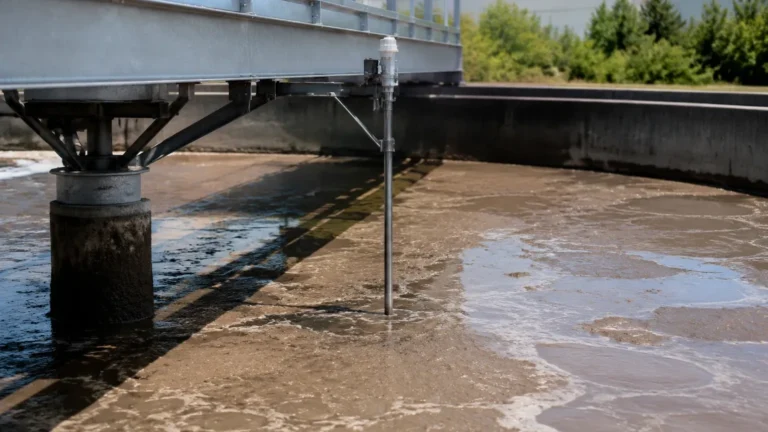
For basic water storage tanks, ultrasonic sensors offer a reliable and cost-effective solution. In wastewater treatment, where foam and vapors are common, radar level meters provide the necessary reliability to prevent overflows. Deep-well and borehole monitoring remain the domain of hydrostatic transmitters due to their ability to be submerged at great depths. Finally, for high-pressure industrial boilers, magnetic level gauges provide the physical robustness and visual redundancy required for safety-critical operations.
By matching the measurement principle to the specific challenges of the site—considering factors like pressure, temperature, and chemical composition—engineers can ensure that their water measurement devices provide accurate data for years of operation. For further technical assistance or to browse specific instrument categories, please refer to the Main Page of our engineering resource center.