Water Well Level Sensor
Water Well Level Sensor
In industrial, municipal, and agricultural water management, the water well level sensor is a critical component for ensuring sustainable groundwater extraction and protecting expensive pumping infrastructure. Accurate level monitoring prevents pump dry-running, assists in calculating aquifer recharge rates, and ensures compliance with environmental regulations. This guide examines the primary measurement technologies, selection criteria, and engineering best practices for implementing level sensors in deep and shallow wells.
Understanding Measurement Principles for Well Monitoring
Choosing the correct water well level sensor requires a fundamental understanding of the physical principles used to detect the water surface or the column of liquid above a fixed point. In the context of industrial automation and water treatment, three primary technologies dominate the market: hydrostatic pressure, ultrasonic time-of-flight, and radar.
Hydrostatic Pressure (Submersible)
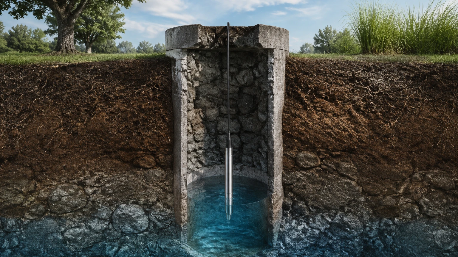
The hydrostatic level transmitter is the most common solution for deep-well monitoring. It operates on the principle that the pressure at a specific depth is proportional to the weight of the liquid column above it. The relationship is defined by the formula: $P = \rho \cdot g \cdot h$, where $P$ is pressure, $\rho$ is the density of the water, $g$ is the gravitational constant, and $h$ is the height of the water column.
A submersible sensor is lowered into the well and remains submerged below the lowest expected water level. The sensor contains a diaphragm that deforms under the weight of the water. This deformation is converted into an electrical signal (typically 4-20mA or RS485 Modbus). To account for changes in atmospheric pressure—which could otherwise introduce errors of up to 30 cm or more—these sensors utilize a vented cable. This cable contains a small capillary tube that allows the internal side of the diaphragm to "breathe," effectively canceling out the barometric pressure acting on the surface of the well.
Ultrasonic (Non-Contact)
Ultrasonic sensors are mounted at the top of the well and emit high-frequency sound pulses. These pulses travel through the air, reflect off the water surface, and return to the sensor. The distance is calculated based on the time-of-flight and the speed of sound in air. While effective for shallow wells or open-top tanks, ultrasonic technology is often limited in deep wells (greater than 15–20 meters) due to signal attenuation and the potential for narrow well casings to cause false reflections (echoes) from the side walls.
Radar (Non-Contact)
Radar level meters, specifically 80GHz high-frequency units, use electromagnetic waves instead of sound. Radar is unaffected by air temperature fluctuations, vapors, or dust within the well. Because radar waves have a much narrower beam angle than ultrasonic waves, they are better suited for narrow boreholes where internal obstructions or wall irregularities might exist. However, radar is generally a higher-cost investment compared to hydrostatic solutions.
Selection Criteria for Industrial Water Well Level Sensors
Selecting a sensor involves more than just matching a depth range. Engineers must evaluate the specific environment of the borehole to ensure long-term reliability. For comprehensive technical specifications and product comparisons, professionals can consult the Main Page of industrial instrument manufacturers like Welk.
1. Measurement Range and Accuracy
The sensor must be rated for the maximum depth of the well, but also calibrated for the specific dynamic range of the water level. For example, a well that is 100 meters deep may only see water level fluctuations between 40 and 60 meters. A sensor with a 0.25% or 0.1% Full Scale (FS) accuracy is standard for professional applications.
2. Material Compatibility
While standard groundwater is typically non-corrosive, brackish water or wells near industrial sites may contain chemicals or high salinity. Stainless steel 316L is the standard housing material, but for high-chloride environments, titanium housings and specialized cables (such as PTFE or Polyurethane) are necessary to prevent corrosion and cable degradation.
3. Signal Output and Integration
For remote monitoring, the 4-20mA analog signal remains a staple due to its ability to transmit over long distances without significant signal loss. However, for digital integration into SCADA systems or IoT gateways, RS485 Modbus is preferred as it allows for the transmission of multiple parameters (e.g., level and temperature) over a single pair of wires.
Installation Guidelines and Best Practices
Proper installation is the single most important factor in the longevity of a water well level sensor. Even the highest quality instrument will fail if the installation does not account for the physical dynamics of the well.
Cable Management and Venting
For hydrostatic sensors, the vented cable must be protected. The capillary tube inside the cable must never be kinked or blocked. It is recommended to terminate the cable in a specialized junction box that includes a breathable desiccant filter. This filter prevents moisture from entering the capillary tube, which could lead to internal condensation and sensor failure.
Positioning Relative to the Pump
The sensor should ideally be placed in a "stilling well"—a small diameter pipe (e.g., 25mm to 50mm PVC) installed inside the main well casing. This stilling well protects the sensor from the turbulence caused by the pump and prevents the sensor cable from becoming entangled with the pump's power lines or discharge piping. If a stilling well is not possible, the sensor should be positioned at least 1 to 2 meters away from the pump intake to avoid pressure fluctuations caused by the suction.
Lightning and Surge Protection
Wells are often located in open areas and act as natural lightning rods. Industrial-grade level sensors should be paired with surge protection devices at both the wellhead and the control panel to prevent damage from induced voltage spikes during storms.
Technical Limitations and Environmental Considerations
Every measurement technology has boundaries that must be respected to maintain data integrity.
* Specific Gravity: Hydrostatic sensors assume a constant liquid density. If the salinity or temperature of the water changes significantly, the density ($\rho$) changes, leading to a linear error in the level reading. If the well water density is not 1.00 g/cm³, the transmitter must be calibrated accordingly.
* Sedimentation: In wells with high silt or sand content, sediment can accumulate around the sensor diaphragm. Periodic cleaning or the use of a protective "caged" sensor nose is necessary to prevent the pressure port from clogging.
* Temperature Compensation: While most high-end sensors include internal temperature compensation, extreme temperature shifts can still affect accuracy. In very deep wells, the water temperature is usually stable, which aids in consistent measurement.
Comparison Table: Level Measurement Technologies
| Feature | Hydrostatic (Submersible) | Ultrasonic (Non-Contact) | Radar (Non-Contact) |
| :— | :— | :— | :— |
| Best Use Case | Deep wells, boreholes | Shallow wells, tanks | Narrow wells, high accuracy |
| Max Range | Up to 500m+ | Typically < 15m | Up to 100m+ |
| Accuracy | High (0.1% to 0.5% FS) | Moderate | Very High (±2mm) |
| Installation | Submerged in liquid | Mounted at wellhead | Mounted at wellhead |
| Maintenance | Periodic cleaning of nose | Keep sensor face clean | Minimal |
| Cost | Economical to Mid-range | Low | High |
| Interference | Turbulence, Density changes | Foam, Vapor, Wind | Obstructions (if beam is wide) |
Frequently Asked Questions (FAQ)
Q: How often should a water well level sensor be calibrated?
A: For most industrial applications, an annual calibration check is recommended. However, if the sensor is used for critical environmental compliance or billing, semi-annual verification against a manual tape measurement is best practice.
Q: Can I use a standard pressure transmitter instead of a submersible one?
A: A standard pressure transmitter mounted at the surface can only measure the pressure at the pump discharge or the wellhead. It cannot measure the static water level or the drawdown level unless it is connected to a bubbler system, which is more complex and requires a constant air supply.
Q: What is the maximum cable length for a submersible level sensor?
A: Most 4-20mA sensors can support cable lengths up to 1,000 meters, provided the power supply voltage is sufficient to overcome the loop resistance. For RS485 Modbus, the limit is typically 1,200 meters without a repeater.
Q: How do I prevent the vented cable from sucking in moisture?
A: Use a vented junction box equipped with a replaceable desiccant cartridge. This ensures that the air reaching the sensor diaphragm is dry, preventing internal corrosion and signal drift.
By following these engineering principles and selecting the appropriate technology for the specific borehole conditions, operators can ensure accurate, long-term monitoring of their water resources. For further assistance in selecting the right instrument for your application, Review product options and application support to find a solution tailored to your specific industrial requirements.