What Is Static Water Level
What Is Static Water Level
In the field of groundwater management, industrial well monitoring, and environmental engineering, understanding the baseline state of a water source is fundamental to ensuring long-term sustainability and operational efficiency. One of the most critical parameters in these applications is the static water level. This measurement serves as the starting point for calculating well yield, determining pump placement, and monitoring the health of an aquifer. For professionals utilizing industrial level measurement instruments, such as those provided on our Main Page, a clear grasp of this concept is essential for selecting the correct technology and ensuring accurate data collection.
Understanding the Definition and Importance
To answer the question of what is static water level, it is defined as the distance from the ground surface (or a specific reference point) to the surface of the water in a well or borehole when the water is at rest. The term "at rest" implies that no pumping has occurred for a sufficient period to allow the water level to stabilize, and the aquifer is not being artificially influenced by nearby extraction.
In practical terms, the static water level represents the equilibrium between the pressure in the aquifer and atmospheric pressure. It is distinct from the "dynamic water level" or "pumping water level," which is the depth of the water while the pump is active. The difference between these two levels is known as "drawdown." Monitoring the static water level over time allows engineers to detect trends such as seasonal fluctuations or long-term depletion of the water table.
Accurate measurement of the static water level is vital for:
1. Pump Selection and Placement: Ensuring the submersible pump is deep enough to remain submerged during drawdown but not so deep that it operates under unnecessary head pressure.
2. Aquifer Health Monitoring: Tracking changes in the water table to prevent over-extraction.
3. Well Efficiency Calculations: Providing the baseline needed to calculate specific capacity (yield per unit of drawdown).
Measurement Principles for Static Water Level
Before selecting a specific instrument, it is important to understand the underlying measurement principles. Different technologies offer varying levels of accuracy, durability, and ease of installation. Welk provides a range of solutions tailored to these specific needs.
Hydrostatic Pressure Measurement
Hydrostatic level transmitters are among the most common tools for measuring static water level in deep wells. The principle is based on the relationship between the height of a liquid column and the pressure it exerts at its base. The formula used is:
$$P = \rho \cdot g \cdot h$$
Where:
* P is the hydrostatic pressure.
* ρ (rho) is the density of the water (typically 1,000 kg/m³ for fresh water).
* g is the acceleration due to gravity (approximately 9.81 m/s²).
* h is the height of the water column above the sensor.
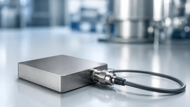
A submersible pressure transducer is lowered into the well to a fixed depth below the expected water level. By measuring the pressure exerted by the water column above it, the sensor can calculate the depth. To ensure accuracy, these sensors must be vented to the atmosphere via a capillary tube in the cable to compensate for changes in barometric pressure.
Ultrasonic (Non-Contact) Measurement
Ultrasonic sensors use the time-of-flight principle. The sensor, mounted at the top of the well, emits a high-frequency sound pulse. This pulse travels through the air, reflects off the water surface, and returns to the sensor. The distance is calculated as:
$$D = \frac{c \cdot t}{2}$$
Where:
* D is the distance to the water surface.
* c is the speed of sound in air (approx. 343 m/s at 20°C).
* t is the total travel time.
While effective for shallow wells or tanks, ultrasonic sensors can be limited by the narrow diameter of boreholes, where signal interference from the well casing (ringing) can occur.
Radar Level Measurement
Radar level meters operate similarly to ultrasonic sensors but use electromagnetic waves (microwaves) instead of sound. High-frequency radar (such as 80GHz) offers a very narrow beam angle, making it ideal for deep, narrow boreholes where internal obstructions or pipe walls might otherwise cause false echoes. Radar is unaffected by air temperature fluctuations, vapors, or dust, providing higher precision for static water level monitoring in industrial environments.
Key Evaluation Criteria for Sensor Selection
When determining how to measure what is static water level in a specific project, several evaluation criteria must be considered to ensure the longevity and reliability of the installation.
1. Measurement Range (Depth): Boreholes can range from a few meters to several hundred meters. Hydrostatic sensors are excellent for extreme depths, provided the cable is reinforced to prevent stretching. Radar is preferred for high-accuracy requirements at moderate to deep ranges.
2. Accuracy and Resolution: For scientific monitoring, a high degree of accuracy (e.g., ±0.1% FS) is often required. For general industrial pump control, standard accuracy may suffice.
3. Environmental Conditions: Is the water corrosive? Is there high humidity or potential for flooding at the wellhead? Submersible sensors must be made of compatible materials like 316L stainless steel or titanium for saline environments.
4. Installation Constraints: If the well is narrow or contains multiple pipes and cables, a non-contact sensor like radar might be easier to maintain than a submersible sensor that could become tangled.
5. Data Integration: Most modern sensors provide 4-20mA, Modbus RS485, or HART outputs, allowing for seamless integration into SCADA systems for remote monitoring.
Practical Selection Table for Industrial Applications
The following table provides a comparison of the primary technologies used to monitor static water levels.
| Technology | Typical Range | Accuracy | Pros | Cons |
| :— | :— | :— | :— | :— |
| Hydrostatic Transmitters | 0–500m+ | High (±0.1% to ±0.5%) | Direct immersion, unaffected by surface foam or narrow pipes. | Requires atmospheric venting; cable can be damaged by debris. |
| Radar (80GHz) | 0–120m | Very High (±1mm to ±2mm) | Non-contact, extremely precise, narrow beam avoids wall interference. | Higher initial cost; requires clear line of sight to water. |
| Ultrasonic | 0–15m | Moderate (±0.25%) | Cost-effective, non-contact. | Sensitive to temperature shifts and narrow well "ringing." |
| Manual Dip Meter | 0–300m | High | Simple, no power required, portable. | Not suitable for continuous automated monitoring. |
Installation and Maintenance Considerations
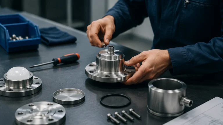
Proper installation is just as important as selecting the right instrument. For hydrostatic sensors, the cable must be secured with a proper strain-relief clamp to prevent the weight of the cable from stretching or snapping the internal wires. Furthermore, the vent tube must be protected by a desiccant filter to prevent moisture from entering the sensor housing, which could lead to internal corrosion or measurement drift.
For radar and ultrasonic installations, the sensor must be mounted perpendicular to the water surface. If the well has a small diameter, a stilling well (a vertical pipe with holes to allow water in) can be used to eliminate surface turbulence and provide a smooth path for the signal. This is particularly useful in applications where the static water level might be disturbed by minor inflows.
Maintenance Checklist:
* Calibration: Check the sensor against a manual dip meter at least once or twice a year.
* Cleaning: For submersible sensors, ensure the sensing diaphragm is free of silt or biological growth.
* Venting: Inspect desiccant filters; if they change color (indicating saturation), replace them immediately.
* Cable Integrity: Check for kinks or abrasions in the cable jacket that could allow water ingress.
Limitations and Common Risks
While modern instrumentation is highly reliable, there are inherent limitations to consider when monitoring what is static water level.
* Barometric Pressure: If using a non-vented hydrostatic sensor, changes in weather can cause errors of several centimeters in the level reading. Always use vented sensors or a secondary barometric pressure sensor for compensation.
* Temperature and Density: Hydrostatic pressure is dependent on fluid density. If the water temperature or salinity changes significantly, the calculated level will drift unless the system is programmed to compensate for density changes.
* Well Casing Interference: In very narrow boreholes, ultrasonic waves can bounce off the sides of the pipe, creating "ghost" echoes. Radar is less prone to this but still requires careful positioning.
* Dynamic Interference: If a nearby well begins pumping, the "static" level in your well may drop due to the cone of depression. It is important to distinguish between a true change in the static level and regional interference.
Frequently Asked Questions (FAQs)
Q: How long should I wait for the water level to become static?
A: This depends on the aquifer's permeability. In high-yield sand and gravel aquifers, the level may stabilize in minutes. In tight clay or deep bedrock, it could take hours or even days. Generally, a 24-hour recovery period is standard for professional testing.
Q: Can I use a radar level meter if there is foam on the water?
A: Foam can absorb radar signals. If the foam is thick and dense, it may cause inaccurate readings. However, 80GHz radar is generally more capable of penetrating light foam than ultrasonic sensors.
Q: What is the difference between static water level and the water table?
A: The water table is the upper surface of the zone of saturation in an unconfined aquifer. The static water level is the specific measurement of that surface within a well. In a confined (artesian) aquifer, the static water level may actually be higher than the top of the aquifer itself due to pressure.
Q: Why is my hydrostatic sensor reading differently than my manual tape?
A: This is often due to a lack of atmospheric compensation, a clogged vent tube, or the sensor being coated in silt. Ensure the sensor is clean and the vent path is clear.
For more detailed technical specifications and to explore our full range of industrial measurement tools, please visit our Main Page. Welk is committed to providing accurate, cost-effective, and reliable solutions for all your level measurement challenges.