Liquid Level Controllers
Liquid Level Controllers
In industrial process automation, maintaining the correct volume of fluids within tanks, vessels, and reservoirs is a critical operational requirement. Liquid level controllers serve as the regulatory hub of these systems, interpreting data from primary sensing elements to manage pumps, valves, and alarms. Whether the application involves wastewater treatment, chemical processing, or oil and gas storage, selecting the appropriate control architecture is essential for preventing overflows, protecting equipment from dry-running, and ensuring process consistency.
Effective level control requires a synergy between the sensor (the "eyes" of the system) and the controller (the "brain"). This guide explores the fundamental principles of level measurement, the types of liquid level controllers available, and the engineering criteria necessary for successful deployment.
Measurement Principles and Sensing Technologies
Before a controller can act, it must receive a reliable signal from a level transmitter or switch. The choice of sensing technology determines the accuracy and reliability of the entire control loop. Industrial level measurement generally falls into two categories: point level detection and continuous level measurement.
Radar Level Measurement (Time-of-Flight)
Radar level meters, particularly frequency-modulated continuous wave (FMCW) units, emit high-frequency microwave pulses toward the liquid surface. The time taken for the signal to reflect back is used to calculate the distance. This non-contact method is highly resistant to changes in temperature, pressure, and vapor space composition. It is often the preferred choice for aggressive chemicals or high-temperature oil and gas applications.
Ultrasonic Level Measurement
Similar to radar, ultrasonic sensors use sound waves. The transducer emits an ultrasonic pulse that reflects off the liquid surface. While cost-effective and reliable for water treatment and simple storage, ultrasonic waves can be affected by heavy foam, dust, or significant air temperature fluctuations, which alter the speed of sound.
Hydrostatic Level Measurement
This principle relies on the relationship between the height of a liquid column and the pressure it exerts at the base of a tank. A hydrostatic transmitter measures this pressure (P = ρgh) to determine the level. This is a robust solution for vented tanks and deep wells, though it requires compensation if the liquid density (specific gravity) changes significantly.
Magnetic Level Gauges and Switches
Magnetic level gauges utilize a float containing a permanent magnet that moves with the liquid level inside a bypass chamber. This motion can actuate external switches or a reed-chain transmitter. For simple on/off control, float switches or vibrating fork switches provide a physical "dry contact" signal when the liquid reaches a specific threshold.
Types of Liquid Level Controllers
Once the sensing technology is established, the signal must be processed. Modern liquid level controllers vary from simple dedicated units to complex integrated systems.
1. On/Off (Bang-Bang) Controllers
These are the simplest forms of controllers, typically used for sump pump management or high-level alarms. When the liquid reaches a high setpoint, the controller turns a pump on; when it drops to a low setpoint, it turns the pump off. This is often achieved using float switches or conductive probes.
2. Digital Process Indicators and Controllers
These standalone units receive a 4-20mA or 0-10V signal from a continuous transmitter. They feature digital displays and programmable relay outputs. They are ideal for local control where a full-scale PLC (Programmable Logic Controller) is not required. Many include "pump-up" or "pump-down" logic and can provide excitation power to the sensor.
3. PID Controllers
Proportional-Integral-Derivative (PID) controllers are used when a precise, constant level must be maintained despite fluctuating inflow or outflow. Instead of simple on/off switching, a PID controller modulates a control valve or a variable frequency drive (VFD) on a pump to maintain a "setpoint" with minimal deviation.
4. PLC and SCADA Integration
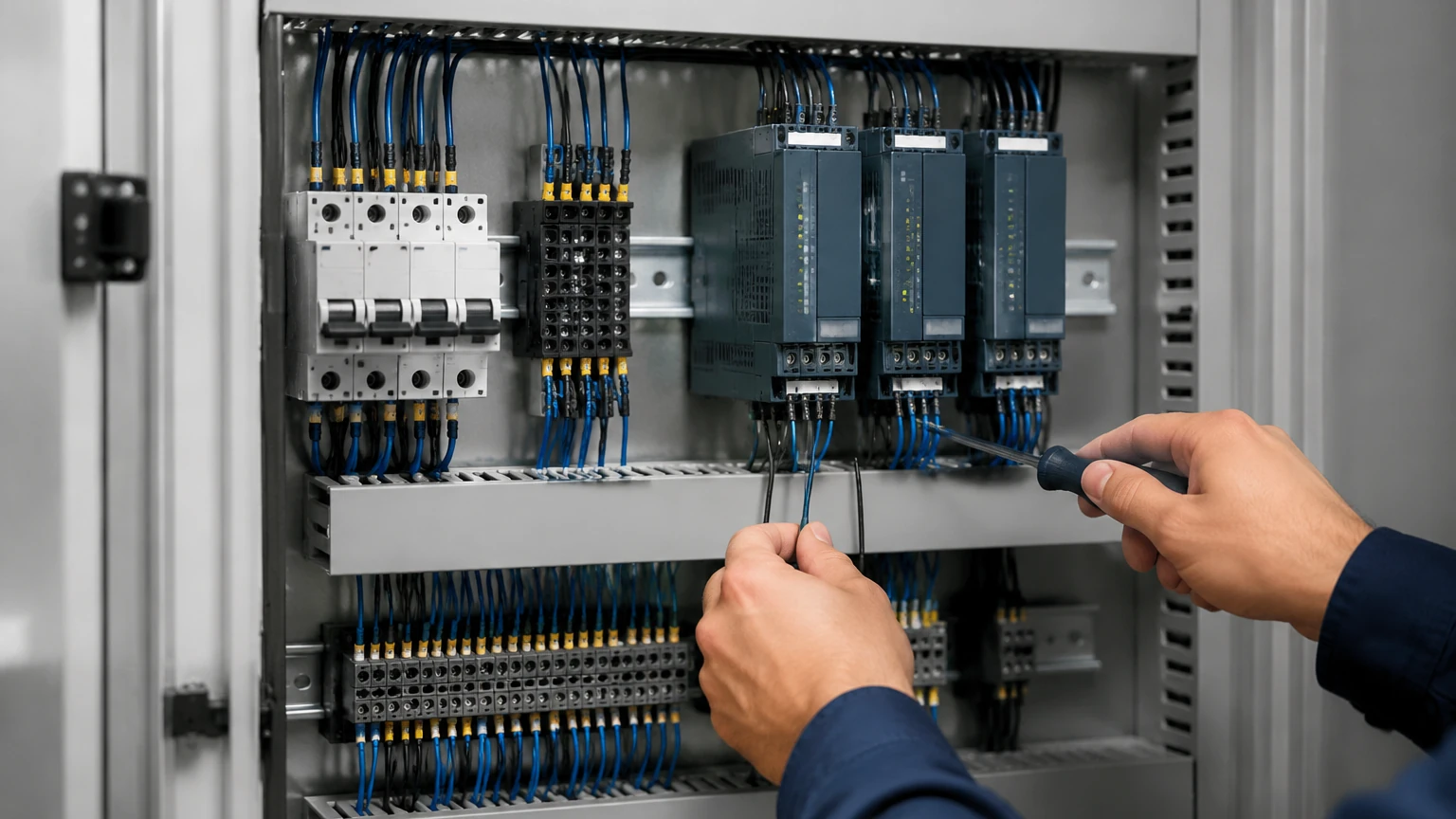
In large-scale industrial automation, level signals are fed into a central PLC. This allows for complex logic, such as alternating between multiple pumps to ensure even wear, or integrating level data with flow rate and temperature for comprehensive process management.
Technical Selection Criteria
Choosing the right combination of sensor and controller requires an analysis of the process environment. Engineers should evaluate the following factors:
Media Properties
* Dielectric Constant: Critical for radar sensors; low-dielectric fluids (like oils) reflect signals less effectively than water.
* Viscosity and Coating: Sticky or viscous fluids can foul mechanical floats or vibrating forks.
* Corrosivity: Aggressive acids require chemically resistant materials such as PTFE or PVDF for wetted parts.
Vessel Geometry
* Internal Obstructions: Agitators, ladders, and heating coils can create "false echoes" for radar and ultrasonic sensors.
* Tank Height: Deep tanks (over 20 meters / 65 feet) may require high-power radar or hydrostatic transmitters.
Environmental Conditions
* Vapor and Foam: Heavy foam can absorb ultrasonic signals, making radar or hydrostatic measurement more suitable.
* Pressure and Temperature: High-pressure vessels require specialized process connections and robust sensor housings.
Selection Comparison Table
| Technology | Measurement Type | Best For | Limitations |
| :— | :— | :— | :— |
| Radar | Continuous | Chemicals, Oils, High Temp | Higher initial cost |
| Ultrasonic | Continuous | Water, Wastewater | Affected by foam and steam |
| Hydrostatic | Continuous | Deep wells, Vented tanks | Requires constant density |
| Magnetic Gauge | Continuous/Point | Visual monitoring, High Pressure | Mechanical moving parts |
| Float Switch | Point | Sump pumps, Alarms | Prone to fouling in dirty liquids |
| Vibrating Fork | Point | Overfill protection | Not for highly viscous media |
Installation and Engineering Considerations
Proper installation is as important as technology selection. Even the most advanced liquid level controllers will fail if the primary sensor is poorly positioned.
1. Dead Zones (Blocking Distance): Both ultrasonic and radar sensors have a "dead zone" near the transducer face where measurement is impossible. Ensure the sensor is mounted high enough that the maximum liquid level does not enter this zone.
2. Mounting Location: Avoid mounting sensors directly above the tank inlet. The turbulence and splashing from incoming fluid will cause signal instability.
3. Stilling Wells: In tanks with heavy agitation or surface turbulence, installing the sensor inside a stilling well (a vertical pipe) can provide a calm surface for more accurate measurement.
4. Cable Routing: Signal cables for 4-20mA transmitters should be shielded and kept away from high-voltage power lines to prevent electromagnetic interference (EMI).
5. Venting: For hydrostatic transmitters in sealed tanks, ensure the sensor is either a differential pressure type or that the tank is properly vented to the atmosphere to avoid measurement errors caused by headspace pressure.
Common Risks and Limitations
While modern instrumentation is highly reliable, certain risks must be mitigated during the design phase:
* Build-up and Scaling: In applications like lime slurry or wastewater, material can build up on the sensor face or mechanical floats. Regular maintenance or the use of non-contact sensors with self-cleaning functions is recommended.
* Specific Gravity Changes: Hydrostatic sensors are calibrated based on a specific liquid density. If the process switches from water to a denser brine, the controller will report an incorrect level unless recalibrated.
* Gas Pockets: In hydrostatic systems, air bubbles trapped in the sensing line can cause "drift" or false readings.
* Signal Loss: Non-contact sensors may lose the signal if the liquid surface becomes extremely turbulent or angled, reflecting the signal away from the receiver.
Frequently Asked Questions (FAQ)
Q: Can one controller manage multiple tanks?
A: Yes, many multi-channel digital controllers can accept inputs from several sensors and manage multiple pump outputs independently or in sequence.
Q: What is the difference between a level transmitter and a level controller?
A: A transmitter measures the level and sends a signal (like 4-20mA). A controller receives that signal and makes a decision (like turning on a pump) based on programmed setpoints.
Q: How do I handle level control in a pressurized tank?
A: For pressurized vessels, differential pressure (DP) transmitters or radar level meters are typically used. DP transmitters compare the pressure at the bottom of the tank to the pressure in the vapor space to calculate the true liquid level.
Q: Are wireless liquid level controllers reliable?
A: Wireless systems are increasingly common for remote monitoring (e.g., agricultural tanks). However, for critical safety-related overfill protection, wired connections are still the industry standard for guaranteed latency and reliability.
Conclusion
Selecting the right liquid level controller is a multi-step process that begins with understanding the physical properties of the liquid and the constraints of the vessel. By matching the measurement principle—whether radar, ultrasonic, or hydrostatic—to the specific application needs, and pairing it with a robust control unit, operators can ensure long-term accuracy and safety. For those seeking specific hardware specifications or customized OEM solutions, it is advisable to Review product options and application support to find the most cost-effective and technically sound configuration for your facility's requirements.