Water Well Monitoring System
Water Well Monitoring System
In industrial water management, municipal supply, and environmental protection, the implementation of a robust water well monitoring system is critical for ensuring the sustainable use of groundwater resources. These systems provide real-time data on water levels, flow rates, and water quality, allowing engineers to prevent pump damage, manage aquifer depletion, and comply with environmental regulations. As industrial automation advances, the integration of high-precision sensors with remote telemetry has transformed well monitoring from manual periodic checks into continuous, data-driven operations.
Selecting the appropriate technology for a water well monitoring system requires a deep understanding of the hydraulic environment, the physical constraints of the wellbore, and the specific data requirements of the project. This guide explores the engineering principles, selection criteria, and installation best practices for modern well monitoring solutions.
Core Measurement Principles for Well Monitoring
Before selecting hardware, it is essential to understand the physics behind the most common level measurement technologies used in groundwater applications. Each method has distinct advantages depending on the well depth, diameter, and water characteristics.
Hydrostatic Pressure Measurement
Hydrostatic level transmitters are the most widely used sensors in deep wells. The principle is based on the relationship between the height of a liquid column and the pressure it exerts at a specific depth. The formula used is $P = \rho \cdot g \cdot h$, where $P$ is pressure, $\rho$ is the density of the liquid, $g$ is gravity, and $h$ is the height of the liquid above the sensor.
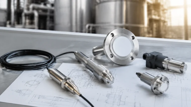
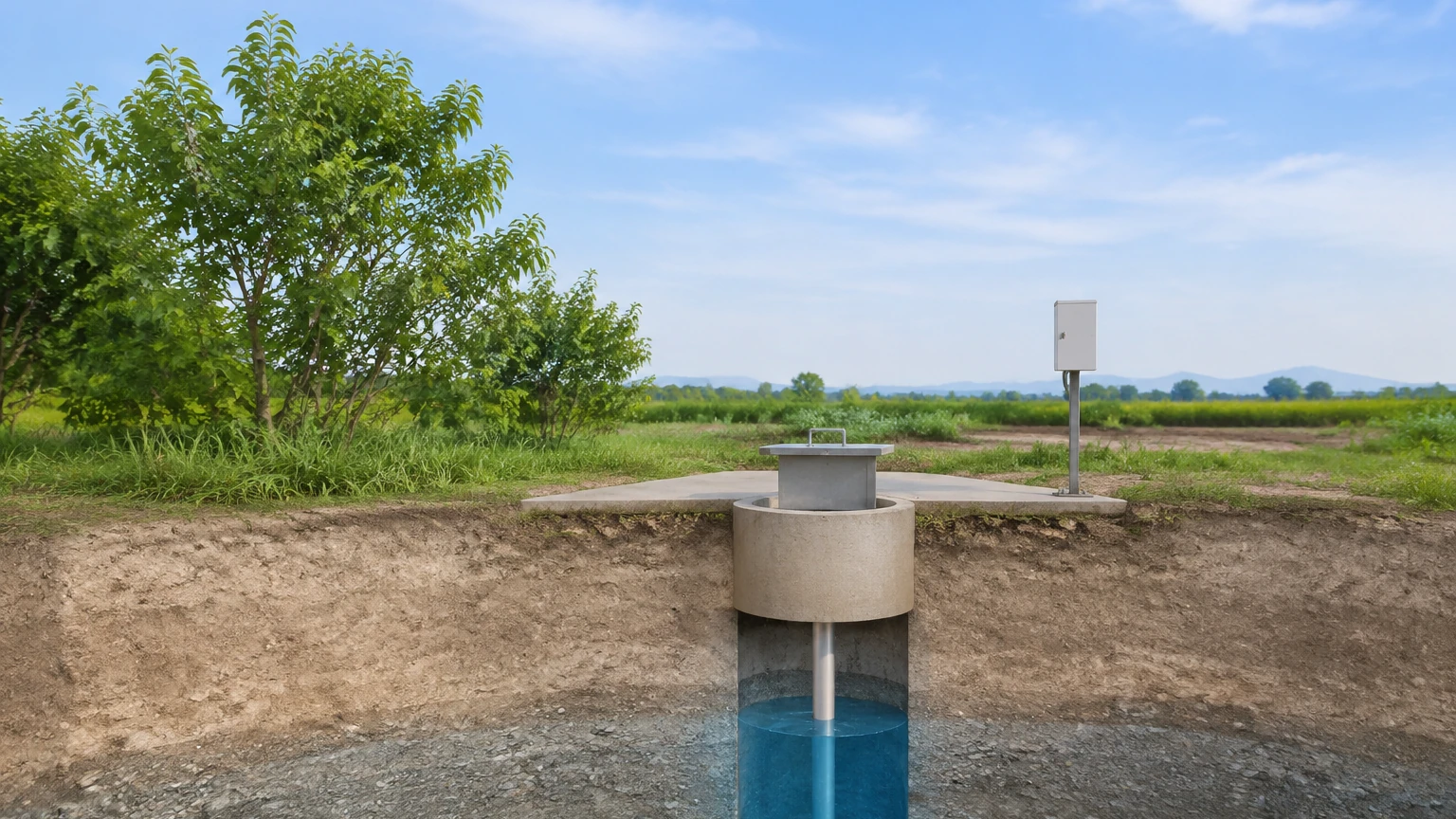
A submersible pressure transducer is lowered into the well to a fixed depth below the lowest expected water level. The sensor measures the total pressure (liquid pressure + atmospheric pressure). To isolate the liquid level, the sensor must compensate for changes in barometric pressure. This is typically achieved using a vented cable that allows atmospheric pressure to reach the back of the sensing diaphragm, effectively canceling out the atmospheric component.
Radar (Non-Contact) Measurement
Radar level meters utilize Frequency Modulated Continuous Wave (FMCW) or pulse technology. The sensor, mounted at the wellhead, emits electromagnetic waves toward the water surface. These waves reflect off the water and return to the sensor. By measuring the time-of-flight or the frequency shift, the system calculates the distance to the water surface.
Modern 80GHz radar technology is particularly effective for well monitoring because it offers a narrow beam angle, which minimizes interference from well casings or internal pipes. Because radar is non-contact, it is immune to the corrosive effects of groundwater and is not affected by changes in liquid density or temperature.
Ultrasonic (Non-Contact) Measurement
Similar to radar, ultrasonic sensors use time-of-flight principles but employ sound waves instead of electromagnetic waves. While cost-effective for shallow wells and open-air tanks, ultrasonic sensors are sensitive to air temperature fluctuations, heavy vapors, and acoustic noise. In deep, narrow wells, the sound waves can reflect off the well walls, leading to inaccurate readings unless a stilling well is used.
Selecting the Right Technology for Your Water Well Monitoring System
Choosing the correct sensor involves balancing accuracy, depth requirements, and maintenance capabilities. The following table provides a comparison of the primary technologies used in a professional water well monitoring system.
| Feature | Hydrostatic Transmitters | Radar (Non-Contact) | Ultrasonic (Non-Contact) |
| :— | :— | :— | :— |
| Primary Application | Deep wells, narrow boreholes | Shallow to medium wells | Shallow wells, sumps |
| Measurement Range | Up to 500m+ | Up to 30m – 120m | Up to 15m – 30m |
| Accuracy | ±0.1% to ±0.5% FS | ±2mm to ±5mm | ±0.25% of range |
| Installation | Submerged in liquid | Mounted at wellhead | Mounted at wellhead |
| Maintenance | Moderate (fouling risk) | Very Low | Low to Moderate |
| Cost | Mid-range | High | Low to Mid-range |
| Environmental Impact | Affected by density/temp | Unaffected by vapors | Affected by air temp/wind |
When designing a system, engineers must also consider the "static water level" (the level when the pump is off) and the "dynamic water level" (the level during pumping). A high-performance water well monitoring system must be capable of tracking these fluctuations rapidly to prevent "dry running" of the pump, which can lead to catastrophic mechanical failure.
Essential Components of a Monitoring System
A complete monitoring solution consists of more than just a sensor. To provide actionable data, the system must integrate several key components:
1. Sensors: As discussed, these may be hydrostatic, radar, or ultrasonic. In some cases, multi-parameter probes are used to measure temperature and conductivity alongside level.
2. Data Loggers: These devices record measurements at set intervals. In remote locations, low-power data loggers are essential to conserve battery or solar power.
3. Telemetry and Communication: Modern systems utilize cellular (4G/5G, NB-IoT, LTE-M), satellite, or radio transmission to send data to a central server. This allows for real-time alerts and remote management.
4. Power Supply: For remote wells, a combination of high-capacity lithium batteries and solar panels is standard. For industrial sites, 24V DC loop power is often available.
5. Software Interface: A cloud-based platform or SCADA integration allows users to visualize trends, generate reports, and set alarm thresholds for low-water conditions.
For those looking to integrate these components into a cohesive industrial setup, you can Review product options and application support to ensure compatibility between sensors and control systems.
Installation Guidelines and Best Practices
Proper installation is the single most important factor in the longevity and accuracy of a water well monitoring system. Even the most expensive sensor will fail if installed incorrectly.
Hydrostatic Sensor Installation
* Venting: Ensure the vent tube in the cable is protected from moisture. Use a desiccant cartridge at the termination point to prevent condensation from forming inside the tube, which can block the reference pressure and cause drift.
* Positioning: The sensor should be placed at least 1 to 2 meters above the bottom of the well to avoid silt and sediment accumulation. It should also be positioned away from the pump intake to minimize turbulence.
* Cable Support: Use a proper cable hanger or Kellems grip to support the weight of the cable in deep wells. Do not rely on the electrical connections to hold the weight.
Non-Contact Sensor Installation
* Beam Clearance: Ensure the radar or ultrasonic beam has a clear path to the water surface. Obstructions like ladders, pipes, or jagged well walls can cause "false echoes."
* Wellhead Sealing: Use appropriate flanges or threaded mounts to seal the wellhead. This prevents debris from entering the well and protects the sensor electronics from environmental exposure.
* Stilling Wells: In wells with high turbulence or significant internal obstructions, installing a stilling well (a vertical pipe with vent holes) can provide a smooth surface for the sensor to measure, significantly increasing accuracy.
Limitations and Operational Challenges
While modern technology has made well monitoring more reliable, several challenges remain that engineers must address during the design phase:
* Biofouling and Scaling: In wells with high mineral content or biological activity, sensors can become coated in scale or biofilm. This is particularly problematic for hydrostatic sensors, where the pressure port can become clogged. Regular cleaning cycles are necessary.
* Lightning and Surges: Because wells are often located in open areas and contain long lengths of conductive cable, they are highly susceptible to lightning strikes. High-quality systems include surge protection at both the sensor and the logger end.
* Signal Attenuation: In very deep wells, transmitting a signal from a submerged sensor over hundreds of meters of cable can result in voltage drops. Using a 4-20mA current loop or a digital RS485 (Modbus) output helps mitigate this issue.
* Aquifer Complexity: In fractured rock aquifers, the water level in the well may not immediately reflect the state of the surrounding aquifer. Understanding the local hydrogeology is necessary to interpret the data correctly.
Frequently Asked Questions (FAQs)
Q: How often should a water well monitoring system be calibrated?
A: For most industrial applications, an annual calibration check is recommended. However, if the data is being used for regulatory compliance or critical process control, semi-annual checks may be required. Manual "dipping" with a water level tape is a common way to verify sensor accuracy in the field.
Q: Can these systems measure water quality as well as level?
A: Yes. Many submersible probes can be equipped with additional sensors for pH, dissolved oxygen, turbidity, and conductivity. However, these multi-parameter probes require more frequent maintenance and calibration than standard level sensors.
Q: What is the typical lifespan of a submersible level transmitter?
A: In clean water environments, a high-quality stainless steel or titanium transmitter can last 5 to 10 years. In corrosive or high-sediment environments, the lifespan may be shorter, necessitating the use of specialized materials or non-contact radar solutions.
Q: Is cellular telemetry reliable for remote well sites?
A: With the advent of NB-IoT (Narrowband Internet of Things), cellular telemetry has become highly reliable even in areas with weak signals. For extremely remote locations where no cellular coverage exists, satellite telemetry is the preferred alternative.
Conclusion
A well-engineered water well monitoring system is an indispensable tool for modern water management. By selecting the right measurement principle—whether it be the rugged reliability of hydrostatic pressure or the high-precision, low-maintenance advantages of 80GHz radar—operators can gain deep insights into their water resources.
When implementing these systems, focus on robust installation practices, atmospheric compensation, and integrated data transmission to ensure long-term success. For detailed technical specifications and to explore a wide range of industrial level measurement instruments, professionals are encouraged to visit the Main Page of Welk's industrial catalog for further guidance and product selection.