Welded Thermowell
Welded Thermowell
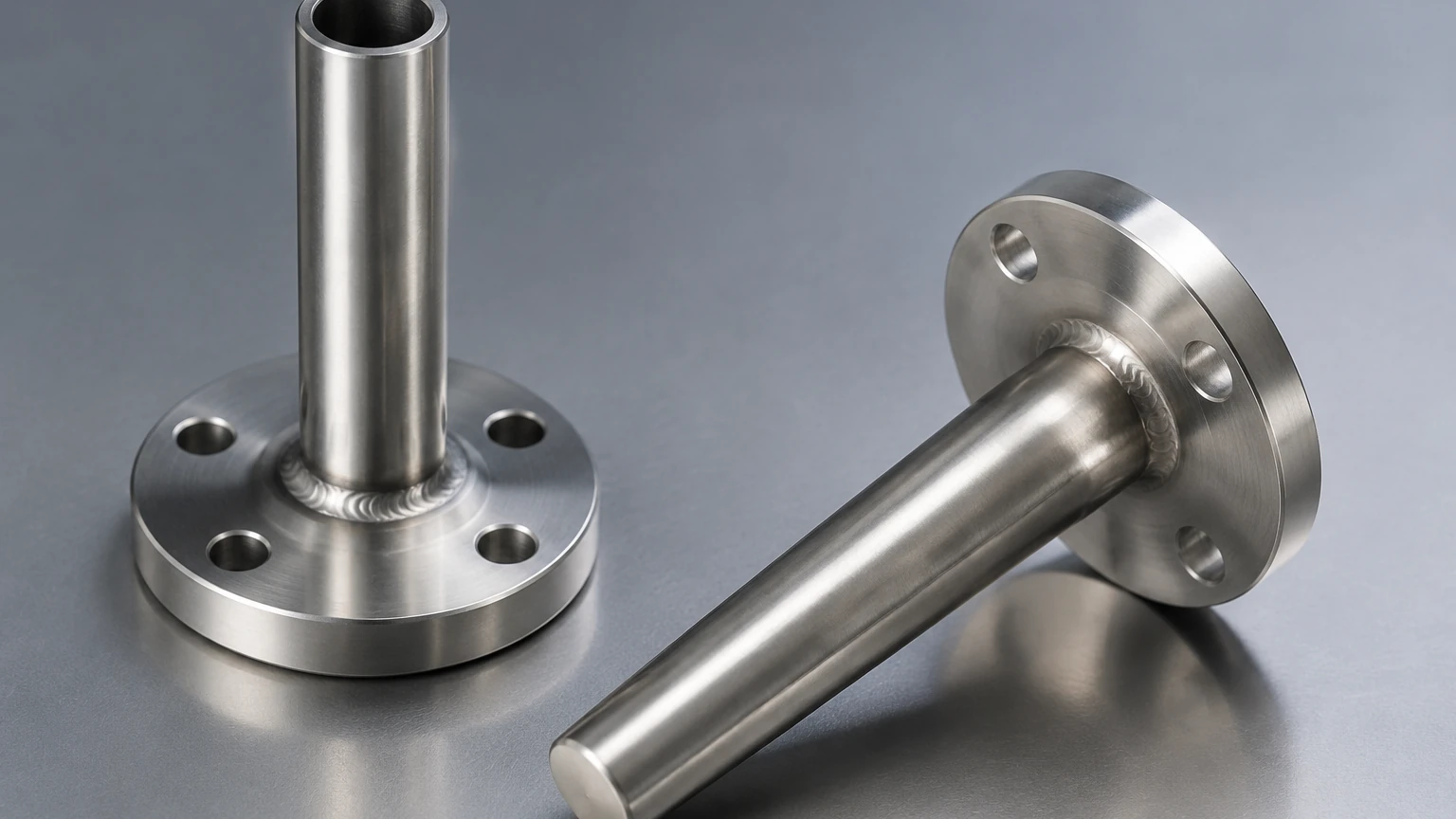
In industrial process control, protecting sensitive instrumentation from the harsh realities of high-pressure, corrosive, or high-velocity fluid environments is a fundamental engineering requirement. A welded thermowell serves as a permanent, pressure-tight barrier designed to house temperature sensors—such as RTDs or thermocouples—while ensuring the integrity of the process vessel or piping. Unlike threaded or flanged variants, a welded thermowell is integrated directly into the system through welding, offering superior leak protection and structural stability in high-stress applications.
For engineers and plant managers involved in industrial automation and level measurement, understanding the nuances of thermowell design is essential. While temperature measurement is a distinct discipline, it is inextricably linked to level measurement accuracy; for instance, the speed of sound in ultrasonic level sensors or the density calculations in hydrostatic level transmitters are both temperature-dependent. This guide explores the principles, selection criteria, and installation best practices for welded thermowells.
Measurement Principles and Function
The primary function of a thermowell is to act as a heat exchanger. It must protect the internal sensor from mechanical damage and chemical attack while allowing thermal energy to pass from the process medium to the sensor with minimal lag.
Heat Transfer Dynamics
When a welded thermowell is installed, the process fluid flows around the exterior of the well. Heat is transferred from the fluid to the thermowell wall via convection, then through the wall via conduction, and finally to the sensor via radiation and conduction through the internal air gap or thermal paste.
To ensure accuracy, the thermowell must have high thermal conductivity and sufficient immersion length to minimize "stem conduction"—a phenomenon where heat travels up the thermowell toward the cooler ambient environment outside the pipe, leading to an artificially low temperature reading. Generally, an immersion length of at least 10 times the thermowell diameter is recommended for liquids, and 15 to 20 times for gases.
Structural Integrity
In high-velocity systems, the fluid flowing past the thermowell creates von Kármán vortices. If the frequency of these vortices (the wake frequency) matches the natural frequency of the thermowell, resonance occurs, which can lead to catastrophic mechanical failure. A welded thermowell, being permanently fused to the process line, provides a rigid connection that is often more resistant to vibration-induced fatigue than threaded connections, provided the weld quality is high.
Types of Welded Thermowells
There are two primary configurations for welded thermowells used in industrial piping and tanks: socket-weld and weld-in (full penetration).
Socket-Weld Thermowells
Socket-weld thermowells are designed to fit into a standard ANSI or DIN socket-weld Union or coupling. The thermowell is inserted into the socket and then secured with a fillet weld. This design is common in smaller pipe sizes (typically 2 inches or 50 mm and below) and provides a very strong, leak-proof joint. However, it does leave a small gap between the thermowell and the socket wall, which can be a site for crevice corrosion in certain chemical applications.
Weld-In Thermowells
Weld-in thermowells are designed to be welded directly into a hole bored into the pipe or vessel wall. These often feature a beveled edge to facilitate a full-penetration groove weld. This method creates the most robust connection possible, essentially making the thermowell part of the pressure vessel itself. It is the preferred choice for high-pressure steam lines and critical oil and gas applications where any risk of leakage must be eliminated.
Selection Criteria and Material Considerations
Selecting the right welded thermowell requires balancing mechanical strength, chemical compatibility, and thermal response. The following table provides a comparison of common thermowell types and their typical applications.
Thermowell Selection Table
| Feature | Socket-Weld | Weld-In (Full Penetration) | Threaded (For Comparison) |
| :— | :— | :— | :— |
| Pressure Rating | High | Very High | Medium |
| Leak Risk | Minimal | Zero (if NDT passed) | Moderate (requires sealant) |
| Installation | Fillet weld to socket | Groove weld to pipe/vessel | Screwed into NPT/BSPT |
| Maintenance | Permanent (requires cutting) | Permanent (requires cutting) | Removable |
| Typical Industry | Chemical, Water Treatment | Power Gen, Oil & Gas | HVAC, Light Industrial |
| Vibration Resistance | High | Excellent | Moderate |
| Standard Sizes | 0.75" to 1.5" (19-38mm) | Custom to fit pipe | 0.5" to 1" (12-25mm) |
Material Selection
The material of the welded thermowell must match or exceed the corrosion resistance of the piping system. Common materials include:
* 316/316L Stainless Steel: The industry standard for water treatment and general chemical applications.
* Hastelloy C-276: Used for highly aggressive acids and chlorides.
* Monel 400: Excellent for hydrofluoric acid and seawater applications.
* Inconel 600: Preferred for high-temperature oxidation resistance.
When specifying a welded thermowell, it is vital to ensure the weld filler material is compatible with both the thermowell and the process piping to prevent galvanic corrosion or weld cracking.
Engineering Design: The Wake Frequency Calculation
For any welded thermowell installed in a flowing stream, engineers must perform a wake frequency calculation according to ASME PTC 19.3 TW. This standard evaluates four critical factors:
1. Oscillating Stress: The stress caused by the fluid flow must not exceed the fatigue limit of the material.
2. Steady-State Stress: The hydrostatic pressure and fluid drag must not exceed the tensile strength of the well.
3. Pressure Rating: The external pressure must not exceed the collapse pressure of the thermowell tip.
4. Frequency Ratio: The ratio of the wake frequency to the natural frequency must be within safe limits (usually < 0.8) to avoid resonance.
If a thermowell fails these calculations, the design must be modified by shortening the immersion length, increasing the root diameter, or using a "Scruton-well" (helical strakes) design to disrupt vortex formation.
Installation Considerations
Proper installation of a welded thermowell is critical for both safety and measurement accuracy. Because these components are permanently attached, errors during installation are costly to rectify.
Welding Procedures
Welding should always be performed by certified welders following approved Welding Procedure Specifications (WPS). For weld-in types, a full-penetration weld is usually required to meet pressure vessel codes (such as ASME Section VIII). Post-weld heat treatment (PWHT) may be necessary depending on the material thickness and the process medium (e.g., to prevent stress corrosion cracking in caustic service).
Orientation and Location
* Elbow Installation: Ideally, a thermowell should be installed in an elbow, pointing upstream. This allows for a longer immersion length and ensures the sensing tip is in the center of the flow profile.
* Perpendicular Installation: If installed perpendicular to the pipe, the tip should reach the center third of the pipe diameter.
* Clearance: Ensure there is enough space to remove the internal sensor (RTD/Thermocouple) for calibration without hitting nearby structures.
Non-Destructive Testing (NDT)
After welding, the joints should be inspected. Common NDT methods include:
* Dye Penetrant Inspection (DPI): To check for surface cracks in the weld.
* X-Ray (Radiography): To ensure full penetration and the absence of internal voids.
* Hydrostatic Testing: Often performed as part of the overall system pressure test.
Limitations and Maintenance
While the welded thermowell offers the highest level of safety against leaks, it has distinct limitations:
1. Permanent Attachment: Unlike threaded or flanged thermowells, a welded unit cannot be easily removed for inspection or if the process requirements change. Removal requires grinding or cutting the weld.
2. Installation Complexity: Requires skilled labor and specialized equipment compared to simple threaded installations.
3. Material Constraints: The thermowell material must be weldable to the pipe material. Dissimilar metal welding is possible but requires specific expertise and filler metals.
From a maintenance perspective, while the thermowell itself is permanent, the internal sensor is replaceable. It is standard practice to use a spring-loaded sensor to ensure the tip of the sensor maintains constant contact with the bottom of the thermowell, optimizing thermal response.
Integration with Level Measurement Systems
In many industrial applications, temperature measurement via thermowells is a supporting function for primary level measurement. For example, in large oil storage tanks, the volume of the product changes significantly with temperature. To calculate the "standard volume," precise temperature data from various depths is required.
Furthermore, in chemical reactors where Welk level instruments are deployed, temperature monitoring via a welded thermowell ensures that the level sensor (such as a high-frequency radar) is operating within its specified temperature range. If the process temperature exceeds the rating of the level meter's electronics, the thermowell-protected temperature sensor can trigger cooling systems or safety interlocks.
For more information on how temperature and level measurement technologies integrate into a complete automation solution, you can Review product options and application support on our Main Page.
Frequently Asked Questions (FAQ)
Q: When should I choose a welded thermowell over a flanged one?
A: Welded thermowells are preferred when the risk of leakage must be zero, such as in high-pressure steam or toxic gas service. Flanged thermowells are typically used when regular removal for inspection is required or when the piping material is not easily weldable.
Q: What is the "1/3 to 2/3" rule in thermowell installation?
A: This rule suggests that the sensing tip of the thermowell should be located between the center third and the middle of the pipe to capture the most representative temperature of the fluid flow, away from the influence of the pipe walls.
Q: Can a welded thermowell be used in plastic piping?
A: No. Welded thermowells are designed for metallic systems. For plastic or FRP (Fiber Reinforced Plastic) piping, flanged or specialized threaded connections are required.
Q: How does the wall thickness of the thermowell affect measurement?
A: A thicker wall increases the mechanical strength and pressure rating but also increases the thermal lag (the time it takes for the sensor to register a change in process temperature). Engineering must balance these two factors based on the process dynamics.
Q: Is a wake frequency calculation necessary for low-velocity water lines?
A: While less critical than in high-velocity steam or gas, it is still best practice to perform the calculation if the velocity exceeds 1-2 m/s (3-6 ft/s) to ensure long-term reliability and compliance with safety standards.
By adhering to these engineering principles and selection guidelines, B2B procurement and engineering teams can ensure that their temperature monitoring infrastructure is as robust and reliable as their level measurement systems. For detailed technical specifications on instrumentation and process protection, visit our Main Page.