Well Level Sensor
Well Level Sensor
In industrial water management, agricultural irrigation, and municipal supply systems, the ability to monitor groundwater levels accurately is critical for operational efficiency and resource sustainability. A well level sensor is a specialized instrument designed to measure the depth of water in boreholes, deep wells, and reservoirs. Selecting the appropriate technology requires a deep understanding of the physical principles governing measurement, the environmental conditions of the well, and the specific requirements of the application.
As a professional manufacturer, Welk provides a range of level measurement solutions tailored to these demanding environments. This guide explores the technical foundations of well level monitoring, compares different sensing technologies, and provides practical engineering advice for selection and installation.
Measurement Principles for Well Level Sensors
Before selecting a well level sensor, it is essential to understand the three primary physical principles used to determine liquid depth: hydrostatic pressure, ultrasonic time-of-flight, and radar wave reflection.
Hydrostatic Pressure Principle
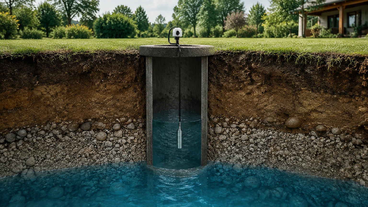
Hydrostatic sensors, often referred to as submersible level transmitters, are the most common choice for deep well applications. The principle is based on the relationship between the pressure at the bottom of a liquid column and the height of that column. The formula used is:
P = ρ × g × h
Where:
* P is the hydrostatic pressure.
* ρ (rho) is the density of the liquid (e.g., water).
* g is the acceleration due to gravity.
* h is the height of the liquid column above the sensor.
In a well, the sensor is lowered to a fixed depth. It measures the pressure exerted by the water above it. To ensure accuracy, these sensors must compensate for atmospheric pressure changes. This is typically achieved using a vented cable that allows the internal side of the sensor diaphragm to remain at atmospheric pressure, ensuring the output reflects only the water column's weight.
Ultrasonic Time-of-Flight
Ultrasonic sensors are non-contact devices mounted at the top of the well. They emit high-frequency sound pulses that travel through the air, reflect off the water surface, and return to the transducer. The distance is calculated based on the speed of sound:
Distance = (Speed of Sound × Time) / 2
While effective for shallow wells or tanks, ultrasonic sensors are sensitive to air temperature fluctuations, heavy vapors, and physical obstructions within the well casing, which can distort the sound waves.
Radar (Microwave) Reflection
Radar level sensors operate similarly to ultrasonic sensors but use electromagnetic waves (microwaves) instead of sound. High-frequency radar (typically 26GHz or 80GHz) is emitted from the sensor head. Because electromagnetic waves travel at the speed of light and are largely unaffected by air temperature, pressure, or vacuum, radar offers higher precision and reliability in challenging environments. The narrow beam angle of 80GHz radar is particularly advantageous in narrow boreholes to avoid false reflections from the well walls.
Comparative Analysis of Sensor Technologies
Choosing the right well level sensor depends on the depth of the well, the presence of turbulence, and the required accuracy. The following table summarizes the key differences between the most common industrial technologies.
Selection Table: Well Level Measurement Technologies
| Feature | Hydrostatic Submersible | Ultrasonic (Non-contact) | Radar (Non-contact) |
| :— | :— | :— | :— |
| Measurement Range | 1m to 500m+ | 0.5m to 30m | 0.3m to 120m |
| Accuracy | ±0.25% to ±0.5% FS | ±0.25% of range | ±1mm to ±3mm |
| Installation | Submerged in liquid | Top-mounted | Top-mounted |
| Media Compatibility | Water, wastewater, oils | Most liquids | Virtually all liquids |
| Atmospheric Impact | Requires vented cable | Affected by temp/vapor | Unaffected |
| Maintenance | Low (periodic cleaning) | Minimal | Minimal |
| Relative Cost | Economical to Medium | Medium | Higher |
For engineers looking to compare specific models and technical parameters, the Welk Main Page provides comprehensive product data sheets and application support.
Key Evaluation Criteria for Well Level Sensors
When specifying a well level sensor for a B2B project, several technical factors must be confirmed to ensure long-term reliability.
1. Measurement Depth and Range
The depth of the well is the primary constraint. For very deep boreholes (exceeding 100 meters or 328 feet), hydrostatic submersible sensors are usually the only practical option due to the signal attenuation challenges faced by top-mounted non-contact sensors in narrow, deep shafts.
2. Material Compatibility
The sensor housing and seals must withstand the chemical composition of the water. While 316L stainless steel is standard for clean water, wells with high salinity (brackish water) or chemical contamination may require specialized materials like Hastelloy or Titanium, and cables made of Polyurethane (PUR) or Polytetrafluoroethylene (PTFE).
3. Signal Output and Integration
Modern industrial systems require seamless integration with PLC or SCADA systems. Common outputs include:
* 4-20mA Analog: The industry standard for long-distance transmission with high noise immunity.
* RS485 Modbus: Ideal for digital communication, allowing multiple sensors on a single bus and providing diagnostic data.
* HART Protocol: Allows digital information to be superimposed on the 4-20mA signal for remote configuration.
4. Narrow Borehole Constraints
In many groundwater monitoring applications, the borehole is narrow (less than 100mm or 4 inches). In these cases, the physical diameter of a hydrostatic sensor must be small (e.g., 19mm or 28mm). If using radar, an 80GHz frequency is preferred because its narrow beam angle prevents the signal from hitting the sides of the pipe, which would cause false echoes.
Installation Considerations and Best Practices
Proper installation is as important as sensor selection. Failure to follow engineering best practices can lead to premature sensor failure or inaccurate data.
Hydrostatic Sensor Installation
* Vented Cable Management: The vented tube inside the cable must remain unobstructed. Use a desiccant cartridge or a specialized vent box at the termination point to prevent moisture from entering the tube, which can cause internal condensation and sensor drift.
* Cable Strain Relief: In deep wells, the weight of the cable itself can cause stretching. Use a proper cable clamp at the wellhead to support the weight and prevent tension on the sensor connection.
* Turbulence Protection: If the well has a high-flow pump, the resulting turbulence can cause the sensor to move, leading to erratic readings. Installing the sensor inside a stilling well (a perforated PVC or metal pipe) will stabilize the unit.
Non-Contact Sensor Installation
* Dead Zone (Blocking Distance): Both ultrasonic and radar sensors have a "dead zone" directly beneath the transducer where measurements cannot be taken. Ensure the sensor is mounted high enough that the maximum water level never enters this zone.
* Beam Path Obstructions: Ensure the path between the sensor and the water surface is clear of ladders, pipes, or pump supports. Even a small bolt protruding from the wall can cause a significant false reflection.
Limitations and Common Risks
While modern well level sensors are highly reliable, certain conditions present risks:
* Lightning and Surges: Wells are often located in open areas, making them susceptible to lightning strikes. Sensors should be equipped with internal surge protection, and external lightning arrestors should be installed on the signal line.
* Sediment Accumulation: In wells with high silt content, sediment can block the pressure port of a hydrostatic sensor. Regular inspection and the use of a flush-diaphragm design can mitigate this.
* Biofouling: In some environments, algae or bacterial growth can coat the sensor. Periodic cleaning is required to maintain accuracy.
* Freezing: If the water surface freezes, non-contact sensors will measure the ice surface, not the liquid level. Hydrostatic sensors must be installed below the frost line to avoid damage from ice expansion.
Frequently Asked Questions (FAQ)
Q: How often should a well level sensor be calibrated?
A: For most industrial applications, an annual calibration check is recommended. However, if the sensor is used for critical billing or regulatory compliance, semi-annual checks may be required. Hydrostatic sensors are more prone to "drift" over several years compared to radar.
Q: Can I use a standard pressure transmitter for well level?
A: No. A standard pressure transmitter is not designed for continuous submersion and lacks the vented cable required to compensate for barometric pressure changes. A dedicated submersible well level sensor is necessary.
Q: What is the maximum distance I can transmit the signal?
A: A 4-20mA signal can typically be transmitted up to 1,000 meters (approx. 3,280 feet) depending on the wire gauge and power supply voltage. For longer distances, RS485 or wireless telemetry systems are preferred.
Q: How do I protect the sensor from pump interference?
A: Use shielded cabling to prevent electromagnetic interference (EMI) from the pump motor. Additionally, physical protection via a stilling well prevents the sensor from being buffeted by the water flow when the pump starts.
Conclusion
Selecting the right well level sensor involves balancing technical requirements with environmental constraints. Hydrostatic submersible sensors remain the workhorse for deep well and borehole monitoring due to their reliability and range. However, for applications where non-contact measurement is preferred, high-frequency radar offers a high-precision alternative that resists environmental interference.
For technical assistance in selecting the right instrumentation for your specific project, or to view our full range of industrial measurement solutions, please refer to our Main Page.