Well Water Depth Sensor
Well Water Depth Sensor
Monitoring groundwater levels is a fundamental requirement in industrial water management, agricultural irrigation, and environmental monitoring. A well water depth sensor provides the critical data needed to manage pump operations, prevent dry-running, and ensure the long-term sustainability of aquifers. Selecting the correct technology requires an understanding of the physical principles of measurement, the specific constraints of the borehole environment, and the integration requirements of the wider control system.
In professional applications, well depth monitoring is rarely just about measuring the distance to the water surface. It involves managing variables such as narrow borehole diameters, significant depths, fluctuating atmospheric pressure, and potential water turbulence. This guide examines the primary sensing technologies used in modern industrial applications and provides a framework for engineering selection.
Measurement Principles for Well Water Depth
Before selecting a well water depth sensor, it is essential to understand how different technologies interact with the well environment. The three most common methods used in industrial contexts are hydrostatic pressure, ultrasonic time-of-flight, and radar (microwave) pulses.
Hydrostatic Pressure Measurement
Hydrostatic sensors are the most widely used technology for deep wells. The principle is based on the relationship between the height of a liquid column and the pressure exerted at its base. The formula $P = \rho \cdot g \cdot h$ (where $P$ is pressure, $\rho$ is liquid density, $g$ is gravity, and $h$ is height) allows the sensor to calculate the depth of water above its diaphragm.
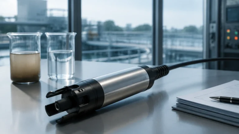
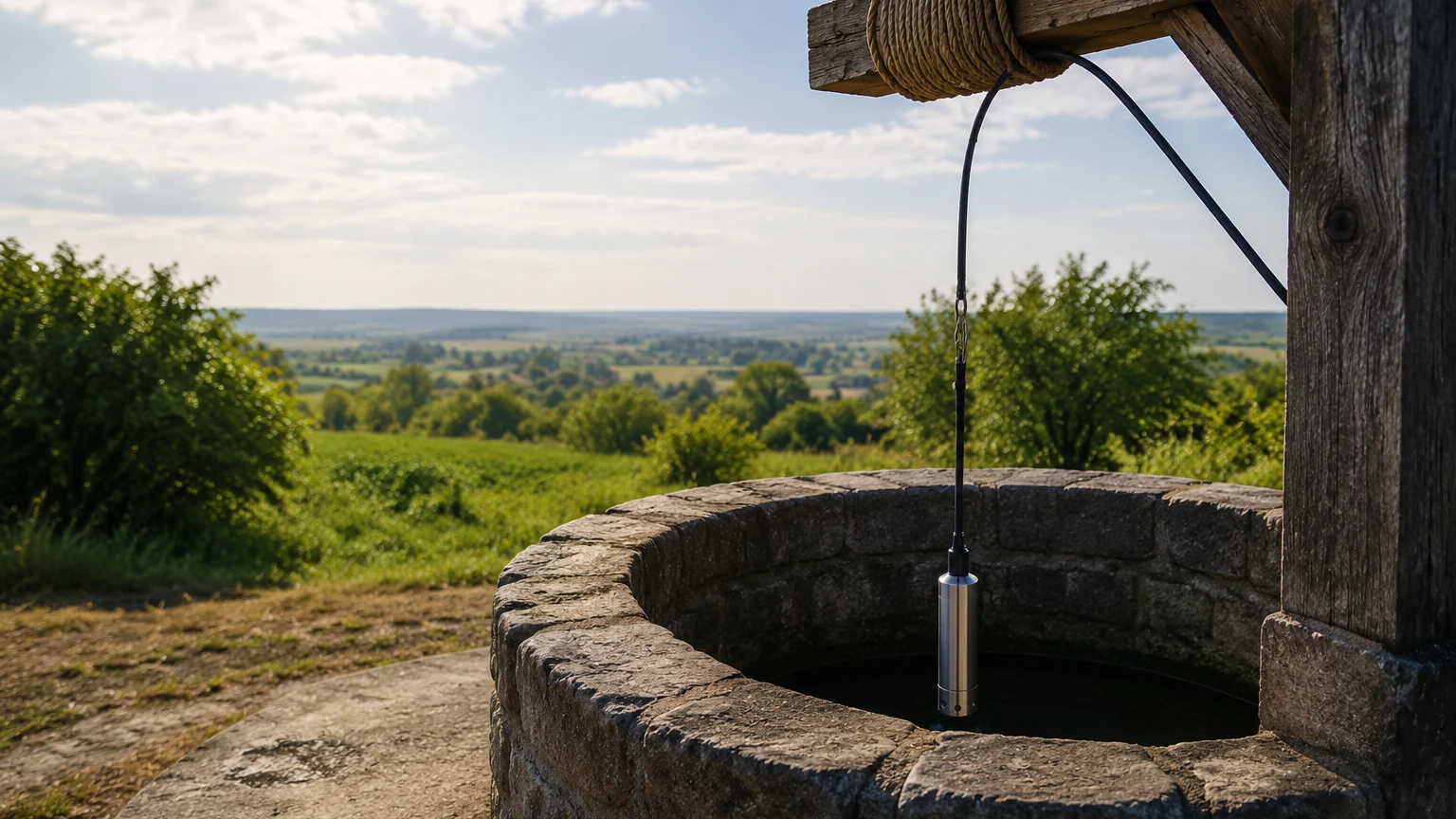
Submersible hydrostatic transmitters are lowered into the well via a specialized cable. This cable contains a small vent tube that allows the sensor to reference the local atmospheric pressure. By venting the back of the sensor diaphragm to the atmosphere, the sensor automatically cancels out fluctuations in barometric pressure, ensuring that the output signal represents only the pressure of the water column. This is critical for accuracy, as a change in weather can otherwise lead to an error of several centimeters in depth reading.
Ultrasonic (Non-Contact) Measurement
Ultrasonic sensors are mounted at the top of the well and emit high-frequency sound pulses toward the water surface. The sensor measures the time it takes for the echo to return. Because the speed of sound in air is approximately 343 m/s (at 20°C), the distance can be calculated based on the time-of-flight.
While non-contact and easy to install, ultrasonic sensors face challenges in well applications. The narrow diameter of a borehole can cause "false echoes" from the well walls or internal piping. Additionally, because the speed of sound varies with air temperature and humidity, these sensors usually require integrated temperature compensation to maintain accuracy over long distances.
Radar (Non-Contact) Measurement
Radar sensors operate similarly to ultrasonic sensors but use high-frequency electromagnetic waves (typically 26GHz or 80GHz) instead of sound. Radar is largely unaffected by temperature, pressure, or air composition within the well. 80GHz radar, in particular, offers a very narrow beam angle, which is ideal for measuring through narrow well heads or boreholes without interference from the casing walls. While more expensive than hydrostatic or ultrasonic options, radar provides the highest level of precision and long-term stability.
Key Evaluation Criteria for Sensor Selection
When specifying a well water depth sensor, engineers must evaluate several technical parameters to ensure the device is fit for purpose. For a broader look at industrial measurement options, engineers can consult the Main Page for detailed specifications on various transmitter types.
1. Measurement Range: Well depths can range from a few meters to several hundred meters. Hydrostatic sensors are generally preferred for very deep wells (up to 500m or more), while non-contact sensors are often limited to 15m–30m in practical well scenarios due to signal attenuation.
2. Accuracy and Resolution: Standard industrial sensors typically offer accuracy between 0.1% and 0.5% of the full scale. For environmental research, higher precision (0.05%) may be required.
3. Borehole Diameter: In many industrial wells, space is at a premium. Submersible sensors must be slim enough (typically 16mm to 28mm in diameter) to pass by pump hardware and cables.
4. Chemical Compatibility: While most well water is neutral, some groundwater may be brackish or contain corrosive elements. In these cases, sensors made from 316L stainless steel, Titanium, or specialized polymers are required.
5. Output Signal: Most industrial systems use 4-20mA analog signals for long-distance transmission without signal loss. However, RS485 (Modbus RTU) is increasingly common for digital integration and multi-drop sensor networks.
Technical Selection Table
The following table compares the three primary technologies based on typical industrial performance metrics.
| Feature | Hydrostatic Submersible | Ultrasonic (Non-Contact) | Radar (80GHz) |
| :— | :— | :— | :— |
| Typical Range | 1m to 500m+ | 0.5m to 15m | 0.1m to 30m+ |
| Accuracy | High (0.1% – 0.5%) | Moderate (0.25% – 1%) | Very High (±2mm) |
| Installation | Submerged in well | Mounted at wellhead | Mounted at wellhead |
| Maintenance | Periodic cleaning | Low | Minimal |
| Environmental Impact | Affected by density changes | Affected by temp/vapor | Unaffected |
| Best For | Deep boreholes, remote sites | Shallow tanks, open wells | Narrow wells, precision |
Installation and Calibration Considerations
Proper installation is as important as sensor selection. Even the most accurate well water depth sensor will provide poor data if installed incorrectly.
Hydrostatic Sensor Installation
* Venting: The atmospheric vent tube in the cable must remain unobstructed. It should terminate in a junction box equipped with a desiccant filter to prevent moisture from entering the tube and causing internal corrosion or sensor drift.
* Stilling Wells: In wells with high-capacity pumps, the water can be turbulent. Installing the sensor inside a "stilling well" (a perforated PVC or steel pipe) protects the sensor from physical damage and minimizes signal noise caused by water movement.
* Cable Support: The cable should be securely clamped at the wellhead to prevent it from slipping or stretching over time, which would alter the depth reference.
Non-Contact Sensor Installation
* Beam Clearance: Ensure the sensor is mounted such that the signal path is clear of any internal obstructions like ladders, pump supports, or casing joints.
* Dead Zone: All non-contact sensors have a "dead zone" (blocking distance) directly beneath the sensor where measurement is impossible. Ensure the sensor is mounted high enough above the maximum water level to account for this.
Common Risks and Limitations
Operating a well water depth sensor in a sub-surface environment involves several risks that must be mitigated during the design phase.
* Lightning and Surges: Because wells are often located in open areas and contain long vertical cables, they are highly susceptible to lightning strikes. High-quality sensors should include integrated surge protection, and the system should be grounded at the wellhead.
* Sediment and Clogging: In some wells, silt or sand can accumulate around a submersible sensor, clogging the pressure port. Regular maintenance involves pulling the sensor and cleaning the diaphragm with a soft cloth or water spray (never use sharp objects).
* Cable Integrity: The outer jacket of a submersible cable is a critical barrier. If it is nicked during installation, water can wick through the cable to the electronics. Care must be taken when lowering sensors past sharp pump flanges.
* Density Fluctuations: Since hydrostatic sensors measure pressure, a change in water density (e.g., due to salinity or temperature changes) will affect the depth reading. If density is expected to change significantly, a multi-parameter sensor or a non-contact method should be considered.
Frequently Asked Questions (FAQ)
Q: How often should a well water depth sensor be calibrated?
A: For most industrial applications, an annual calibration check is recommended. This involves comparing the sensor reading to a manual tape measurement. If the deviation exceeds the required tolerance, the offset can usually be adjusted in the PLC or the transmitter’s internal settings.
Q: Can I use a hydrostatic sensor in a well that is not vented?
A: If the well is sealed and pressurized, a standard vented hydrostatic sensor will not work correctly because it cannot reference the internal pressure of the well. In these cases, a differential pressure sensor or a non-vented absolute pressure sensor (with a separate barometric sensor for compensation) must be used.
Q: What is the maximum distance I can run the cable from the well to the control room?
A: Using a 4-20mA current loop, signals can typically be transmitted over 1,000 meters depending on the wire gauge and power supply voltage. For longer distances, RS485 or wireless telemetry systems are preferred.
Q: Will foam on the water surface affect the measurement?
A: Foam is a significant challenge for ultrasonic sensors as it absorbs the sound waves. Radar is more resilient but can still be affected by very thick, dense foam. Hydrostatic sensors are completely unaffected by surface foam.
By understanding these principles and constraints, facility managers and engineers can select a well water depth sensor that provides reliable, long-term data for critical water infrastructure. For further information on product selection and technical support, refer to the Main Page of our engineering resource center.