Well Water Monitoring System
Well Water Monitoring System
Effective groundwater management is a cornerstone of modern industrial, agricultural, and municipal infrastructure. A well water monitoring system provides the essential data required to manage water resources sustainably, ensure regulatory compliance, and protect pumping equipment from damage. Whether managing a single deep well for a remote facility or a network of boreholes for a municipal water supply, selecting the right measurement technology is critical for long-term reliability.
In industrial contexts, such as those served by Welk, level measurement instruments must withstand harsh environments, including high humidity, potential chemical exposure, and significant depths. This guide examines the primary measurement principles, system architectures, and selection criteria necessary for implementing a robust monitoring solution.
Measurement Principles for Well Water Monitoring
Before selecting a specific instrument, it is vital to understand the physics behind the most common measurement technologies. In a well water monitoring system, three primary methods are utilized: hydrostatic pressure, ultrasonic time-of-flight, and radar (microwave) reflection.
Hydrostatic Level Measurement
Hydrostatic level transmitters are the most common choice for deep well applications. The principle is based on the relationship between the height of a liquid column and the pressure it exerts at a specific point. The formula used is $P = \rho \cdot g \cdot h$, where $P$ is pressure, $\rho$ is the density of the fluid (water), $g$ is the acceleration due to gravity, and $h$ is the height of the water above the sensor.
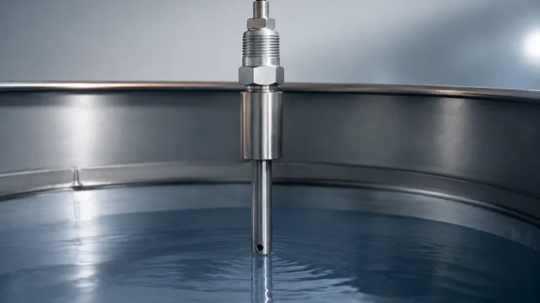
In practice, a submersible pressure transducer is lowered into the well to a fixed depth below the lowest expected water level. The sensor measures the pressure exerted by the water column above it. To ensure accuracy, the system must account for changes in atmospheric pressure. This is typically achieved through a vented cable that allows the internal side of the sensor diaphragm to remain at atmospheric pressure, effectively "canceling out" the air pressure acting on the water surface. This provides a true "gauge pressure" reading that corresponds directly to the water level.
Ultrasonic Level Measurement
Ultrasonic sensors are non-contact devices that emit high-frequency sound pulses. These pulses travel through the air, reflect off the water surface, and return to the sensor. The distance is calculated based on the time it takes for the pulse to return (Time-of-Flight) and the speed of sound in air.
While ultrasonic sensors are advantageous because they do not touch the water, they are often limited in well applications by the narrow diameter of the borehole. If the sound beam hits the side of the well casing before reaching the water, it can produce false readings. Furthermore, temperature gradients within the well can affect the speed of sound, requiring integrated temperature compensation.
Radar Level Measurement
Radar level meters, particularly those operating at 80GHz, represent the high end of non-contact technology. They function similarly to ultrasonic sensors but use electromagnetic waves instead of sound. Radar is unaffected by air temperature, pressure, or vapor. The narrow beam angle of high-frequency radar makes it much more suitable for narrow well casings than traditional ultrasonic sensors. However, the cost is generally higher, and the sensor must be mounted at the top of the well with a clear line of sight to the water surface.
Key Components of a Well Water Monitoring System
A complete well water monitoring system is more than just a sensor. It requires an integrated suite of components to transform physical measurements into actionable data.
1. The Primary Sensor: As discussed, this is usually a hydrostatic transmitter, ultrasonic sensor, or radar meter. It must be rated for the specific depth and environmental conditions of the well.
2. Data Logger or RTU (Remote Terminal Unit): This component collects the signals (typically 4-20mA or RS485 Modbus) from the sensor. It often includes internal memory to store data in the event of a communication failure.
3. Communication Interface: Modern systems utilize various protocols to transmit data to a central server. Options include cellular (NB-IoT, GPRS, or 4G), satellite for remote locations, or hardwired connections for industrial sites with existing SCADA infrastructure.
4. Power Management: In remote wells, solar power systems with battery backups are standard. In industrial plants, the system is usually powered by a 24V DC supply from the control cabinet.
5. Software and Visualization: The end-user interacts with the data through a dashboard that shows real-time levels, historical trends, and alarm statuses (e.g., low-level alerts to prevent pump dry-running).
Selection Criteria and Comparison Table
Choosing the right technology depends on the specific requirements of the well, such as depth, diameter, and the presence of turbulence. For a comprehensive overview of available instruments and technical support, engineers can refer to the Main Page to review product options and application support.
| Feature | Hydrostatic Transmitters | Ultrasonic Sensors | Radar Level Meters |
| :— | :— | :— | :— |
| Measurement Type | Contact (Submersible) | Non-contact | Non-contact |
| Max Depth | Up to 500m+ | Typically < 15m | Up to 30m – 120m |
| Accuracy | High (0.1% to 0.5% FS) | Moderate (0.25% FS) | Very High (±2mm) |
| Installation | Lowered into well | Top-mounted | Top-mounted |
| Narrow Wells | Excellent | Poor (Beam spread) | Good (Narrow beam) |
| Maintenance | Periodic cleaning | Low | Very Low |
| Cost | Cost-effective | Moderate | High |
Installation Best Practices
The longevity and accuracy of a well water monitoring system depend heavily on proper installation. Even the most advanced sensor will fail or provide incorrect data if installed poorly.
Positioning the Sensor
In a hydrostatic setup, the sensor should be placed below the lowest drawdown level but above any silt or sediment at the bottom of the well. Ideally, it should be secured to the pump discharge pipe or a dedicated stilling well using stainless steel cable ties to prevent movement during pump startup.
Cable Management and Venting
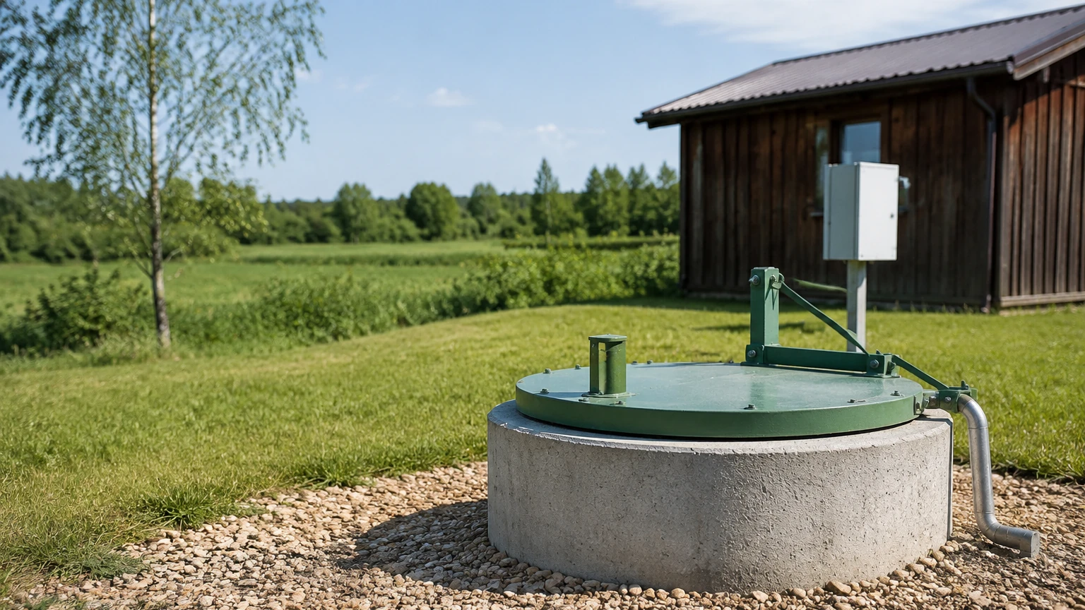
For hydrostatic sensors, the vented cable is the most vulnerable component. The vent tube must remain unobstructed. A desiccant cartridge should be installed at the top of the vent tube to prevent moisture from entering the tube and condensing, which can lead to sensor failure or measurement drift. The cable should also be protected from sharp edges at the wellhead using a conduit or a specialized well cap.
Stilling Wells
If the well experiences significant turbulence or has a high flow rate near the sensor, a stilling well (a perforated pipe) should be installed. This provides a calm environment for the sensor, reducing "noise" in the level data and protecting the instrument from physical debris.
Operational Limitations and Challenges
While modern systems are highly reliable, engineers must be aware of potential limitations:
* Sediment and Biofouling: In some groundwater environments, mineral deposits or biological growth can clog the pressure port of a hydrostatic sensor or the diaphragm of an ultrasonic device. Regular inspection and cleaning are necessary.
* Lightning and Surges: Wells are often located in open areas, making them susceptible to lightning strikes. High-quality systems should include surge protection at both the sensor and the controller level.
* Signal Attenuation: In very deep wells, the voltage drop over long cable runs can affect 4-20mA signals. In these cases, RS485 (Modbus) digital communication is preferred as it is more resistant to noise and signal loss over long distances.
* Atmospheric Compensation: If using a non-vented hydrostatic sensor (absolute pressure), a second barometric sensor must be installed at the surface to subtract atmospheric pressure from the total pressure measured underwater.
Frequently Asked Questions (FAQ)
Q: How often should a well water monitoring sensor be calibrated?
A: Most industrial-grade sensors from manufacturers like Welk are designed for long-term stability. However, it is recommended to perform a field check every 6 to 12 months by comparing the sensor reading against a manual water level tape (dip meter).
Q: Can these systems be used in saltwater or brackish wells?
A: Yes, but material selection is critical. For hydrostatic sensors, 316L stainless steel is standard, but for high-salinity environments, Titanium or Hastelloy housings and specialized cables (such as PTFE) are required to prevent corrosion.
Q: What is the benefit of using a digital RS485 output over a 4-20mA analog signal?
A: RS485 Modbus allows for the transmission of multiple parameters (e.g., level and temperature) over a single pair of wires. It also provides better diagnostic capabilities and is less prone to inaccuracy caused by electromagnetic interference (EMI) or long cable lengths.
Q: How do I protect the system from freezing?
A: In cold climates, the sensor itself is usually safe because it is submerged below the frost line. However, the surface electronics and the vent tube must be protected. Using an insulated enclosure and ensuring the vent tube terminates in a dry, protected area is essential.
Conclusion
A well-designed well water monitoring system is an invaluable asset for any facility relying on groundwater. By understanding the measurement principles of hydrostatic, ultrasonic, and radar technologies, and by adhering to strict installation and maintenance standards, operators can ensure a continuous supply of accurate data. This data not only protects expensive pumping equipment but also provides the insights needed for responsible water stewardship in an increasingly water-scarce world. For those seeking specific hardware recommendations or customized OEM/ODM services, consulting with a professional manufacturer is the recommended next step to ensure the selected instruments meet the unique demands of the application.