What Are Thermowells
What Are Thermowells
In the realm of industrial process control, the integrity of measurement data is paramount. While level measurement instruments like radar or ultrasonic sensors provide critical volume data, temperature measurement is equally vital for process safety, quality control, and the compensation of density-related level readings. At the heart of these temperature measurement systems lies a critical component: the thermowell.
Understanding what are thermowells requires looking beyond their simple appearance as metal tubes. They are precision-engineered pressure vessels designed to protect sensitive temperature elements from the harsh environments found in industrial piping and tanks. This guide explores the engineering principles, selection criteria, and installation best practices for thermowells in B2B industrial applications.
Measurement Principles and Functional Role
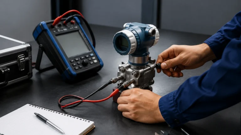
A thermowell acts as a protective barrier between a temperature sensor—typically a Resistance Temperature Detector (RTD) or a Thermocouple—and the process medium (liquid, gas, or steam).
The Heat Transfer Interface
The fundamental principle of a thermowell is thermal conduction. The thermowell is installed directly into the process flow. Heat from the process fluid is conducted through the wall of the thermowell into its internal bore, where the temperature sensor is housed. To ensure accuracy, the sensor must be in physical contact with the bottom of the thermowell bore, often aided by a spring-loaded mounting mechanism. This minimizes the air gap, which would otherwise act as an insulator and slow down the response time.
Process Isolation
The primary functional advantage of a thermowell is that it allows for the removal and replacement of a temperature sensor without breaking the process seal. In a pressurized system, such as a chemical reactor or a high-pressure steam line, removing a bare sensor would result in a catastrophic leak. By using a thermowell, the process remains contained, allowing maintenance teams to calibrate or replace sensors while the plant remains operational.
Types of Thermowells and Shank Designs
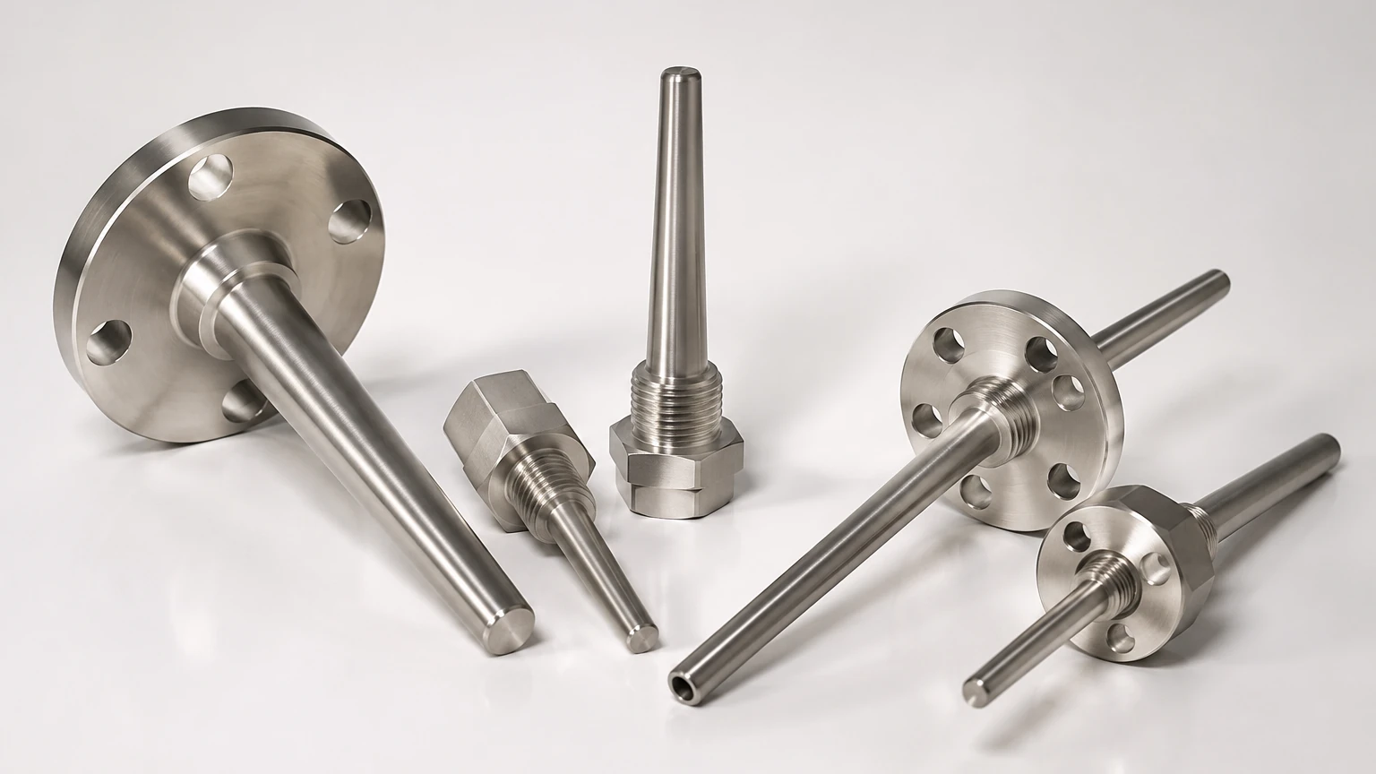
Thermowells are classified by their connection type and the geometry of their "shank" (the portion that extends into the process). Selecting the right type is critical for balancing structural integrity with measurement sensitivity.
Connection Types
1. Threaded Thermowells: These are screwed into a NPT or BSP thread on a pipe or vessel. They are cost-effective and common in lower-pressure applications where frequent removal is not required.
2. Flanged Thermowells: These feature a flange that bolts to a mating flange on the process equipment. They are the standard for high-pressure, high-temperature, and highly corrosive environments, such as those found in oil and gas refineries.
3. Socket Weld Thermowells: These are welded into a socket coupling. They provide a high-integrity, leak-proof connection but are permanent and difficult to replace.
4. Weld-in Thermowells: Directly welded into the process wall, these offer the highest pressure rating but require cutting the pipe for replacement.
Shank Geometries
* Straight Shank: The diameter is uniform along the entire insertion length. These are easy to manufacture but have a higher mass, leading to slower response times.
* Tapered Shank: The diameter decreases linearly from the process connection to the tip. This design provides a high strength-to-weight ratio, making it ideal for high-velocity flows.
* Stepped Shank: The diameter drops abruptly near the tip (e.g., from 19 mm to 12.7 mm). This reduces the thermal mass at the sensing point, providing the fastest response time while maintaining a robust base.
Practical Selection Table
When specifying thermowells, engineers must match the material and design to the specific process conditions. The following table provides a general guideline for material selection based on common industrial environments.
| Material | Common Grade | Temperature Limit (Approx.) | Typical Application |
| :— | :— | :— | :— |
| Stainless Steel | 316/316L | 850°C (1560°F) | Water treatment, food and beverage, general chemical. |
| Carbon Steel | A105 | 425°C (800°F) | Low-pressure steam, non-corrosive hydrocarbons. |
| Monel | Alloy 400 | 538°C (1000°F) | Sea water, hydrofluoric acid, marine engineering. |
| Hastelloy | C-276 | 1000°C (1832°F) | Highly corrosive acids, chlorine, sour gas. |
| Inconel | Alloy 600 | 1150°C (2100°F) | High-temperature furnaces, heat treating. |
Installation Considerations and Calculations
Proper installation is as important as material selection. A poorly installed thermowell can lead to inaccurate readings or mechanical failure.
Insertion Length (U-Length)
The insertion length, often referred to as the "U-length," is the distance from the tip of the thermowell to the underside of the thread or flange. For accurate measurement, the sensitive portion of the sensor must be fully immersed in the moving fluid. A general rule of thumb for liquid processes is an insertion length equal to 1/3 to 2/3 of the pipe diameter. In gas applications, where heat transfer is less efficient, the insertion length may need to be longer to prevent "stem conduction" (heat escaping through the thermowell wall to the outside atmosphere).
Wake Frequency and Velocity Limits
When a fluid flows past a thermowell, it creates vortices (the Von Karman effect). If the frequency of these vortices matches the natural frequency of the thermowell, resonance occurs. This can cause the thermowell to vibrate violently and eventually snap off due to fatigue. Engineers must perform a Wake Frequency Calculation (per ASME PTC 19.3 TW) to ensure the thermowell can withstand the fluid velocity, pressure, and temperature of the specific application.
Orientation
Thermowells should ideally be installed against the flow or at a 90-degree angle. Installing with the flow is generally avoided as it can create stagnant pockets that do not reflect the true process temperature.
Limitations and Common Risks
While thermowells are essential, they introduce certain variables into the measurement loop that must be managed.
1. Time Lag: Because the heat must pass through the thermowell wall and the internal air gap, there is a delay in response compared to a bare sensor. In fast-cycling processes, this lag must be accounted for in the control logic.
2. Conduction Error: If the portion of the thermowell outside the pipe is much colder than the process, heat will flow out of the well, causing the sensor to read lower than the actual process temperature. Proper insulation of the thermowell head can mitigate this.
3. Corrosion and Erosion: In high-velocity flows containing particulates (slurries), the thermowell tip can erode over time. Regular inspection is required to ensure the wall thickness has not reached a dangerous limit.
The Relationship Between Temperature and Level Measurement
In many industrial setups, temperature data from thermowells is used to enhance the accuracy of level measurement. For instance, hydrostatic level transmitters calculate the level based on the pressure exerted by a liquid column. Since the density of liquid changes with temperature, a thermowell-mounted sensor provides the data necessary to correct the level calculation in real-time. For comprehensive details on integrating these technologies, professionals often visit the Main Page of instrumentation providers to review compatible transmitter and sensor configurations.
Frequently Asked Questions (FAQs)
Q: How do I choose between a tapered and a straight thermowell?
A: Tapered thermowells are generally preferred for high-velocity flows because they have a higher natural frequency and are less likely to suffer from resonance. Straight thermowells are suitable for low-velocity or static applications where cost is a primary concern.
Q: Can I use a thermowell in a pipe smaller than 4 inches (100 mm)?
A: Yes, but it often requires installing the thermowell in an elbow or using a pipe "tee" to expand the flow area, ensuring the thermowell does not significantly restrict the flow or cause a large pressure drop.
Q: What is the "bore" diameter?
A: The bore is the internal diameter of the thermowell. Standard bore sizes are 6.5 mm (0.260 inches) and 9.5 mm (0.385 inches), designed to accommodate standard 6 mm or 1/4-inch sensors.
Q: How often should thermowells be inspected?
A: This depends on the corrosivity and velocity of the process. In high-wear environments, annual ultrasonic thickness testing is recommended. In clean, non-corrosive services, they may last the life of the plant.
Conclusion
Thermowells are indispensable components in modern industrial processing. They provide the necessary protection for temperature sensors while ensuring the safety and continuity of the process. By carefully considering material compatibility, shank geometry, and wake frequency limits, engineers can ensure reliable temperature data that supports both safety and efficiency. Whether you are managing a water treatment facility or a complex chemical refinery, selecting the right thermowell is a foundational step in robust instrumentation design. For those looking to specify complete measurement solutions, including radar and ultrasonic systems, consulting a professional manufacturer like Welk ensures that all components work in harmony to provide accurate process insights.