What Is a Cts Sensor
What Is a Cts Sensor
In the landscape of industrial automation and process control, technical acronyms often overlap across different disciplines. When engineering professionals ask "what is a cts sensor," the answer typically depends on the specific industrial context: electrical power monitoring or environmental water analysis. In the field of level measurement and fluid management—areas where Welk specializes—understanding these sensors is crucial for protecting equipment like pumps and ensuring the quality of the media being measured.
This guide explores the primary types of CTS sensors, their operating principles, and how they integrate with level measurement technologies to provide a comprehensive process control solution.
Defining the CTS Sensor in Industrial Applications
There are two primary definitions for a CTS sensor in a B2B industrial environment:
1. Current Transformer Sensor (CTS): These are electrical devices used to measure alternating current (AC). They produce a proportional current in their secondary circuit, allowing for the monitoring of high-voltage power lines or industrial motors. In level control systems, they are frequently used to monitor pump health.
2. Conductivity, Temperature, and Salinity Sensor (CTS): These are multi-parameter probes used in water treatment and chemical processing. They measure the electrical conductivity of a liquid, its thermal state, and the concentration of dissolved salts.
For a professional managing a tank farm or a water treatment facility, both types of sensors may be present. A hydrostatic level transmitter might measure the volume of a tank, while a CTS (Conductivity) sensor monitors the water quality, and a CTS (Current Transformer) monitors the pump extracting that water.
Operating Principles of Current Transformer (CTS) Sensors
When referring to electrical monitoring, a CTS sensor operates on the principle of electromagnetic induction. It consists of a primary winding, a magnetic core, and a secondary winding.
Electromagnetic Induction
When AC flows through a primary conductor (such as a heavy-duty power cable for an industrial pump), it creates a varying magnetic field around the conductor. The magnetic core of the CTS sensor concentrates this field, inducing a current in the secondary winding. This secondary current is significantly lower than the primary current, typically standardized to 1A or 5A, making it safe for meters and control units to process.
Load Monitoring in Level Systems
In applications involving level switches or continuous level sensors, a Current Transformer CTS is often installed in the control panel. By monitoring the current draw of a pump, the system can detect:
* Dry Running: A sudden drop in current when a level sensor fails to stop a pump after the tank is empty.
* Blockages: A spike in current caused by a clogged impeller.
* Mechanical Wear: Gradual increases in current over time indicating motor fatigue.
The Role of Conductivity-Temperature-Salinity (CTS) Sensors in Water Treatment
In the context of fluid analysis, a CTS sensor is an integrated probe that provides three critical data points. This is particularly relevant when using level measurement instruments in desalination, wastewater treatment, or chemical mixing.
Measurement Principles
* Conductivity: The sensor applies an AC voltage to electrodes immersed in the liquid. The resulting current flow is proportional to the ion concentration in the fluid. In some advanced models, inductive (toroidal) sensors are used to avoid electrode fouling.
* Temperature: Usually measured via a Platinum Resistance Thermometer (e.g., PT100 or PT1000). Temperature is critical because conductivity varies significantly with thermal changes (typically 2% per degree Celsius).
* Salinity: This is a derived value. The sensor's internal processor uses the conductivity and temperature data, applying a standard algorithm (such as the Practical Salinity Scale) to calculate the salt content.
Key Selection Criteria for Industrial CTS Sensors
Selecting the right sensor requires an evaluation of the physical environment and the required precision. The following table provides a comparison for selection purposes:
| Feature | Current Transformer (CTS) | Conductivity-Temp-Salinity (CTS) |
| :— | :— | :— |
| Primary Metric | Amperage (A) | Conductivity (mS/cm or µS/cm) |
| Installation | Control Panel / Cable Wrap | In-line Pipe / Submerged Tank |
| Output Signal | 0-5A, 4-20mA, or Modbus | 4-20mA, RS485, or SDI-12 |
| Accuracy | 0.2% to 1.0% Class | ±1% of Reading |
| Maintenance | Low (Non-contact) | Moderate (Requires cleaning) |
| Housing Material | Nylon/Plastic (UL94-V0) | PVC, Titanium, or Stainless Steel |
Practical Selection Considerations
When choosing a CTS sensor for electrical monitoring, ensure the "Window Diameter" is sufficient for your cable size. For a standard 50mm (approx. 2 inches) power cable, a sensor with a 60mm (2.36 inches) opening is recommended to allow for heat dissipation. For conductivity-based CTS sensors, material compatibility is the priority. If the media is highly corrosive, such as concentrated brine or acids, a PEEK or Teflon-coated probe is necessary.
Integration with Level Measurement Systems
Modern industrial automation relies on the synergy between different sensor types. On the Main Page of a comprehensive instrumentation strategy, level meters and CTS sensors work together to provide a full picture of the process.
Automated Pump Protection
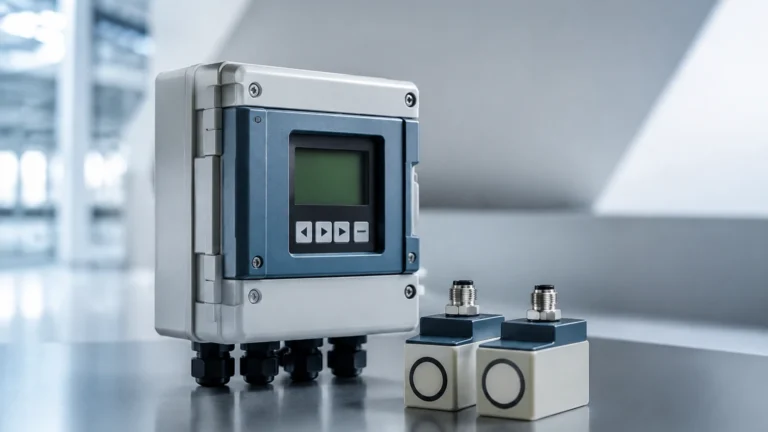
A common configuration involves a Welk ultrasonic level sensor paired with an electrical CTS sensor. The ultrasonic sensor monitors the liquid level in a sump. If the level drops below a safety threshold (e.g., 300mm / 11.8 inches), the controller sends a stop command to the pump. Simultaneously, the CTS sensor monitors the pump's actual current. If the current drops before the level sensor reaches the setpoint, it indicates a prime loss or a pipe burst, triggering an emergency shutdown.
Quality-Controlled Filling
In chemical blending, a radar level meter tracks the volume of a tank while a Conductivity CTS sensor monitors the concentration of the mix. Once the conductivity reaches the target setpoint (indicating the correct chemical ratio) and the level meter confirms the tank is at its 10m (32.8 ft) capacity, the process moves to the next stage. This dual-verification prevents the production of off-spec batches.
Installation Best Practices and Maintenance
To ensure long-term reliability, follow these engineering guidelines during installation:
For Current Transformer CTS Sensors:
* Polarity Matters: Ensure the "K-L" or "P1-P2" orientation matches the direction of current flow to maintain correct phase relationships in power metering.
* Secondary Circuit Safety: Never open the secondary circuit of a CT while the primary is energized. This can generate dangerously high voltages across the secondary terminals.
* Shielding: Use twisted-pair shielded cables for the secondary signal to prevent EMI from high-voltage lines from distorting the data.
For Conductivity CTS Sensors:
* Avoid Air Pockets: Install the sensor in a section of pipe that is always full. In horizontal pipes, mount the sensor at a 45-degree angle from the bottom to avoid both sediment buildup and air bubbles.
* Calibration: Conductivity sensors require periodic calibration using standard reference solutions. Frequency depends on the "fouling factor" of the liquid.
* Submergence Depth: For tank installations, ensure the probe is submerged at least 150mm (approx. 6 inches) below the minimum liquid level to avoid surface turbulence interference.
Limitations and Common Challenges
While CTS sensors are robust, they have specific limitations that engineers must account for:
1. Saturation (Electrical CTS): If the primary current exceeds the sensor's rated capacity, the magnetic core will saturate, leading to non-linear outputs and inaccuracies.
2. Polarization (Conductivity CTS): In simple two-electrode sensors, ions can build up near the electrodes, creating a "foul" reading. This is why 4-electrode or inductive sensors are preferred for high-salinity applications.
3. Temperature Lag: In rapid-flow systems, the temperature element of a CTS probe may lag behind the actual fluid temperature, leading to temporary errors in the temperature-compensated conductivity reading.
Frequently Asked Questions (FAQs)
Q: Can a Current Transformer CTS sensor measure DC current?
A: No. Standard CTS sensors based on electromagnetic induction only work with Alternating Current (AC). For DC measurement, a Hall Effect sensor is required.
Q: How often should a water quality CTS sensor be cleaned?
A: In clean water applications, every 6 months is usually sufficient. In wastewater or cooling towers with high biological activity, monthly inspection and cleaning with a soft brush or weak acid solution may be necessary.
Q: What is the difference between a split-core and solid-core CTS?
A: A solid-core CTS requires you to disconnect the cable to thread it through the sensor, offering higher accuracy. A split-core CTS can be clamped around an existing cable without disconnecting power, which is ideal for retrofitting in active plants.
Q: Does salinity affect level measurement?
A: Yes, if you are using a hydrostatic level transmitter. Salinity changes the density of the liquid. Since hydrostatic sensors calculate level based on pressure and density ($P = \rho gh$), a change in salinity without recalibration will result in a level measurement error. Integrating a CTS sensor allows the system to dynamically compensate for these density changes.
Conclusion
Understanding "what is a cts sensor" is the first step in optimizing an industrial process. Whether you are monitoring the electrical load of a critical pump or the chemical composition of a process fluid, these sensors provide the granular data necessary for safety and efficiency. When integrated with high-quality radar or ultrasonic level measurement tools, CTS sensors transform a simple tank into an intelligent, self-monitoring system. For more information on selecting the right instrumentation for your specific application, you can review product options and application support on our Main Page.