What Is a Downstream O2 Sensor
What Is a Downstream O2 Sensor
In the landscape of industrial process control and emissions monitoring, understanding the precise composition of exhaust gases is as critical as monitoring the liquid levels in a storage tank. Among the various analytical tools used in combustion and environmental control, the oxygen (O2) sensor—specifically the downstream configuration—plays a pivotal role. This article explores the engineering principles, functional importance, and selection criteria for downstream O2 sensors within industrial and heavy-duty applications.
Measurement Principles of Oxygen Sensors
Before identifying the specific role of a downstream placement, it is essential to understand the electrochemical principles that allow these sensors to function. Most industrial oxygen sensors utilize a solid-state electrolyte, typically made of zirconium dioxide (ZrO2), also known as zirconia.
The Zirconia Principle (Nernst Cell)
The core of a zirconia O2 sensor is a ceramic element coated with thin layers of platinum on both sides, which act as electrodes. One side of the ceramic is exposed to the exhaust gas (the process side), while the other side is exposed to a reference gas, usually ambient air with a known oxygen concentration of approximately 20.9%.
At temperatures above 315°C (approximately 600°F), the zirconia ceramic becomes conductive to oxygen ions. If there is a difference in oxygen partial pressure between the process side and the reference side, oxygen ions migrate through the ceramic lattice. This movement of ions creates an electrical potential (voltage) across the platinum electrodes. This voltage is calculated using the Nernst equation:
* High Voltage (0.6V to 0.9V): Indicates a "rich" environment with low oxygen content.
* Low Voltage (0.1V to 0.4V): Indicates a "lean" environment with high oxygen content.
Titania Sensors
While less common in large-scale industrial applications than zirconia, titania (TiO2) sensors operate on a resistance-changing principle. Instead of generating a voltage, the electrical resistance of the titania element changes in response to the oxygen concentration in the gas stream. These sensors do not require a reference air supply, making them more compact but often more sensitive to temperature fluctuations.
Defining the Downstream O2 Sensor
In any system involving a catalytic process—such as an industrial thermal oxidizer, a stationary engine, or a complex chemical scrubber—sensors are placed at different stages of the flow.
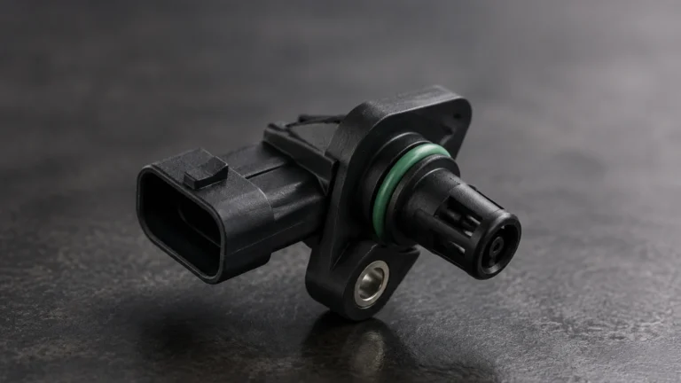
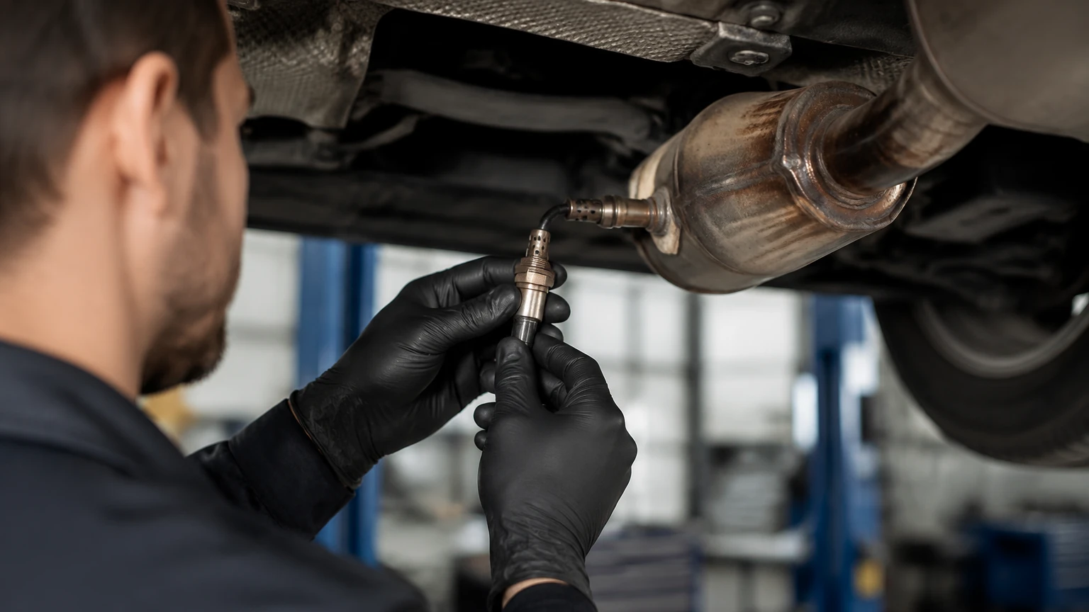
What is a downstream o2 sensor? It is the secondary oxygen sensor located after the catalytic converter or emission control device. While the "upstream" sensor (located before the catalyst) is primarily responsible for real-time feedback control of the air-fuel ratio or the chemical reagent injection, the downstream sensor serves as a diagnostic and fine-tuning tool.
The Relationship Between Upstream and Downstream
In a healthy industrial combustion system, the upstream sensor will show a rapidly fluctuating signal as the control system adjusts the mixture to maintain stoichiometry. Conversely, the downstream sensor should ideally show a much more stable, "lazy" signal. This stability indicates that the catalytic process is successfully consuming residual oxygen and pollutants. If the downstream signal begins to mimic the upstream signal, it is a primary indicator of catalyst degradation or "breakthrough."
Key Evaluation Criteria for Industrial O2 Sensors
Selecting the correct sensor for an industrial environment requires evaluating the chemical compatibility and the physical demands of the process. Below is a selection table for comparing common sensor characteristics.
Selection Table: O2 Sensor Specifications
| Feature | Zirconia (Narrowband) | Wideband (UEGO) | Titania |
| :— | :— | :— | :— |
| Measurement Range | Near Stoichiometric | 0.7 to 2.0 Lambda | Near Stoichiometric |
| Operating Temp. | 300°C – 850°C | 600°C – 900°C | 300°C – 800°C |
| Output Signal | 0.1V – 0.9V DC | 0mA – 5mA (Current) | Resistance Change |
| Reference Air | Required | Required | Not Required |
| Response Time | < 100 ms | < 50 ms | < 150 ms |
| Typical Application | Catalyst Monitoring | Combustion Control | Compact Systems |
Heater Integration
Industrial downstream sensors are almost always "heated" sensors. Because the exhaust gas cools as it passes through the catalytic stages, it may fall below the 315°C threshold required for the zirconia to become ionically conductive. Integrated ceramic heaters ensure the sensor reaches operating temperature quickly and remains stable regardless of the process load.
Installation and Engineering Considerations
Proper installation is paramount to ensuring the longevity and accuracy of a downstream O2 sensor. Engineers should adhere to the following guidelines:
1. Orientation: The sensor should be installed at an angle of at least 10 degrees above the horizontal plane. This prevents moisture (condensate) from collecting inside the sensor housing, which can cause thermal shock and crack the ceramic element upon startup.
2. Distance from Catalyst: The sensor must be placed sufficiently far downstream to ensure the gas is well-mixed, but close enough to avoid excessive thermal lag. Typically, this is 50mm to 150mm from the catalyst exit.
3. Wiring and Shielding: In industrial environments with high electromagnetic interference (EMI) from pumps and motors, signal wires must be shielded. The low-voltage output of a zirconia sensor is highly susceptible to noise.
4. Seal Integrity: Any air leaks upstream of the downstream sensor will introduce "false oxygen," leading the system to erroneously report that the catalyst is failing or that the mixture is too lean.
Limitations and Common Failure Modes
Despite their robust design, downstream O2 sensors are susceptible to specific industrial hazards:
* Silicone Poisoning: Silicone vapors from gaskets or lubricants can coat the platinum electrodes, creating a barrier that prevents oxygen ions from reaching the ceramic. This results in a "shifted" or unresponsive signal.
* Soot and Particulate Fouling: In heavy-oil combustion or diesel applications, soot can clog the protective louvers of the sensor, slowing the response time significantly.
* Lead and Phosphorus Contamination: These elements can chemically bond with the catalyst and the sensor electrodes, permanently degrading their performance.
* Thermal Shock: If liquid water hits a hot sensor element, the ceramic will shatter instantly. This is a common issue in systems with frequent start-stop cycles where condensation is prevalent.
Integrating Gas Analysis with Level Measurement
In a comprehensive B2B industrial framework, gas analysis and level measurement are two halves of the same operational efficiency coin. For instance, in a chemical wastewater treatment facility, monitoring the liquid level in a reagent tank using a radar level meter ensures that there is enough chemical available for the scrubbing process. Simultaneously, the downstream O2 sensor monitors the exhaust of the thermal oxidizer to ensure the scrubbing was effective.
By integrating these data points into a centralized PLC or SCADA system, plant managers can achieve a holistic view of process health. To explore the full range of instrumentation required for these integrated systems, including advanced radar and ultrasonic sensors, professionals should consult the Main Page for technical specifications and application support.
FAQs
1. Can a downstream O2 sensor affect fuel economy?
In most modern industrial engine controllers, the downstream sensor is used for "Long Term Fuel Trim" (LTFT) adjustments. While the upstream sensor handles the immediate changes, the downstream sensor accounts for the aging of the catalyst and the upstream sensor itself. Therefore, a faulty downstream sensor can lead to sub-optimal combustion efficiency and increased fuel consumption.
2. How often should industrial O2 sensors be replaced?
Unlike level meters, which often have no moving parts and can last for decades, O2 sensors are consumable items. In clean-burning natural gas applications, they may last 10,000 to 15,000 hours. In high-sulfur or high-particulate environments, replacement may be required every 2,000 to 5,000 hours.
3. What is the difference between a 3-wire and a 4-wire sensor?
A 3-wire sensor uses a single wire for the heater power, one for the signal, and uses the sensor body as a common ground. A 4-wire sensor provides a dedicated ground wire for the signal, which is significantly more accurate in industrial settings as it eliminates "ground loop" interference.
4. Why does my downstream sensor show a steady 0.45V?
A steady 0.45V signal often indicates that the sensor has not yet reached its operating temperature or that there is a break in the signal circuit. The controller defaults to this "bias voltage" until the sensor is ready to provide a real reading.
Conclusion
The downstream O2 sensor is a vital component in the quest for industrial efficiency and environmental compliance. By understanding the electrochemical principles of zirconia and titania elements, and by following strict installation protocols, engineers can ensure reliable monitoring of catalytic processes. When combined with accurate primary process measurements—such as those found on the Welk Main Page—these sensors empower facilities to operate safely, cleanly, and cost-effectively.