What Is a Turbidity Sensor
What Is a Turbidity Sensor
In industrial liquid processing, water treatment, and chemical manufacturing, the clarity of a fluid is often as critical as its level or flow rate. To quantify this clarity, engineers rely on specialized analytical instruments. But exactly what is a turbidity sensor, and how does it function within a complex automated system?
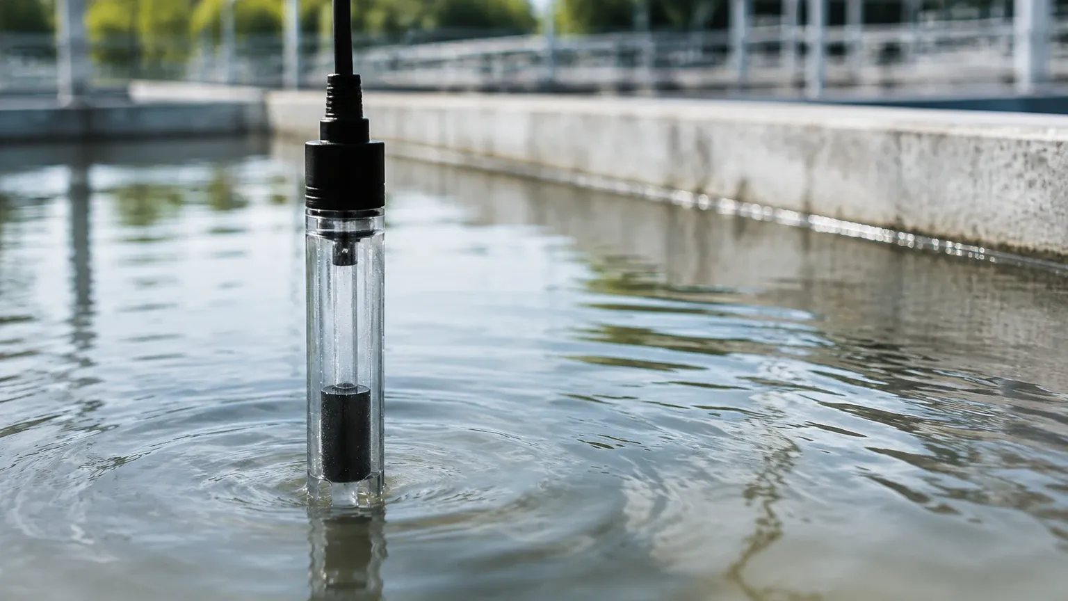
Turbidity is an optical characteristic of a process fluid that describes the degree to which light is scattered or absorbed by suspended particles. These particles can include silt, clay, organic matter, algae, or even microscopic air bubbles. A turbidity sensor is the primary tool used to provide a real-time, quantitative measurement of this "cloudiness," allowing operators to maintain product quality, ensure regulatory compliance, and protect downstream equipment.
Understanding Turbidity in Industrial Processes
Before selecting instrumentation, it is essential to define the physical property being measured. Turbidity is not a direct measurement of the weight of suspended solids (Total Suspended Solids or TSS), though the two are often correlated. Instead, it is an expression of the optical interference caused by those solids.
In industrial environments, high turbidity can indicate several process issues:
* Filtration Failure: A sudden spike in turbidity after a filter bed indicates breakthrough.
* Chemical Precipitation: In chemical dosing, turbidity changes signal the formation of solids.
* Product Consistency: In the food and beverage industry, turbidity ensures that products like juices or beer meet specific clarity standards.
* Environmental Compliance: Wastewater discharge must meet strict turbidity limits to prevent ecological damage in receiving water bodies.
How a Turbidity Sensor Works: Measurement Principles
To answer the question of what is a turbidity sensor in a technical sense, one must look at the interaction between light and matter. Most modern industrial sensors utilize one of three primary optical principles, often governed by international standards such as ISO 7027 or EPA 180.1.
1. Nephelometry (90° Scattered Light)
This is the most common method for measuring low to medium turbidity. An infrared or white light source is beamed into the fluid. A detector is positioned at a 90-degree angle relative to the light path. When light hits a particle, it scatters in all directions. The detector measures the intensity of the light scattered at that specific 90-degree angle. The more particles present, the higher the intensity of the scattered light. This method is highly sensitive and is the standard for drinking water applications.
2. Transmission (180° Attenuated Light)
In this method, the detector is placed directly opposite the light source. The sensor measures the amount of light that passes through the fluid without being absorbed or scattered. As the concentration of particles increases, the light intensity reaching the detector decreases. This principle is generally used for high-turbidity applications, such as sludge monitoring or thick chemical slurries, where light cannot penetrate deeply enough for scattering measurements.
3. Backscatter (90° to 180°)
For extremely high concentrations of solids where the fluid is nearly opaque, backscatter sensors are used. These sensors measure the light that reflects back toward the source. This is particularly useful in industrial wastewater and mining applications.
Key Evaluation Criteria for Industrial Turbidity Sensors
When evaluating a sensor for a specific project, engineers must look beyond the basic definition of what is a turbidity sensor and consider the operational environment. The following criteria are essential for ensuring long-term accuracy:
* Measurement Range: Turbidity is typically measured in NTU (Nephelometric Turbidity Units) or FNU (Formazin Nephelometric Units). Sensors may range from 0–10 NTU for ultra-pure water to 0–4,000+ NTU for raw wastewater.
* Light Source: Infrared (IR) light (approx. 860 nm) is preferred in colored liquids to avoid interference from dissolved organic matter. White light (Tungsten) is often required by specific EPA regulations for drinking water.
* Process Temperature and Pressure: Industrial sensors must withstand the physical rigors of the pipe or tank. Standard sensors usually handle up to 50°C, while specialized high-temperature versions can exceed 100°C.
* Material Compatibility: The sensor body (often PVC, Stainless Steel, or PEEK) and the optical window (Glass, Sapphire, or Quartz) must be resistant to the chemical composition of the process fluid.
Selection Guide: Comparing Turbidity Measurement Technologies
The following table provides a comparison of common turbidity sensor configurations used in industrial automation.
| Sensor Type | Principle | Typical Range | Primary Application | Advantage |
| :— | :— | :— | :— | :— |
| Nephelometric | 90° Scattering | 0–400 NTU | Drinking water, Filter monitoring | High sensitivity at low levels |
| Absorption | 180° Transmission | 100–4,000 NTU | Wastewater, Chemical processing | Simple design, good for high loads |
| Ratio Method | Multiple Angles | 0–2,000 NTU | Variable particle sizes | Compensates for color interference |
| Submersible Probe | Scattered/Backscatter | 0–1,000+ NTU | Open channels, Tanks | No sampling system required |
For comprehensive level and analytical measurement solutions, you can Review product options and application support on our Main Page.
Installation Guidelines and Best Practices
Even the most advanced turbidity sensor will provide inaccurate data if installed incorrectly. Because these are optical instruments, the physical environment of the installation point is paramount.
1. Bubble Management
Air bubbles are the primary enemy of turbidity measurement. To a sensor, a microscopic air bubble looks exactly like a solid particle, leading to false high readings.
* Solution: Install sensors in vertical pipes with upward flow to ensure the pipe remains full and bubbles are carried away. Alternatively, use a "de-bubbler" or a stilling well in tank installations.
2. Flow Velocity
In pipe installations, the flow must be fast enough to prevent particles from settling on the sensor lens but slow enough to avoid cavitation or excessive turbulence that creates bubbles. A velocity of 0.5 to 2.0 meters per second (m/s) is generally ideal.
3. Avoiding Wall Interference
In small-diameter pipes, light can reflect off the internal pipe wall and return to the detector, causing a "stray light" error.
* Solution: Use matte black internal coatings or ensure the sensor is positioned far enough from the back wall. In tank installations, maintain a minimum distance (usually 100mm to 200mm) from the floor and walls.
4. Accessibility for Maintenance
Turbidity sensors require periodic calibration and cleaning. Ensure the sensor is installed with isolation valves (for pipe mounts) or retractable assemblies so it can be removed without shutting down the entire process line.
Limitations and Common Risks in Turbidity Measurement
While understanding what is a turbidity sensor helps in selection, knowing its limitations prevents operational failures.
* Fouling and Biofilm: Over time, algae, minerals, or oils can coat the optical window. This "fouling" will cause the sensor to drift. Many modern sensors include integrated wipers or ultrasonic cleaning systems to mitigate this.
* Color Interference: If a liquid is highly colored (like tea or industrial dye) but clear, a white-light sensor may misinterpret the light absorption as turbidity. Using an infrared light source (ISO 7027) helps solve this.
* Particle Size and Shape: Turbidity sensors assume a standard particle type (usually Formazin). If your process involves very large or very small particles, the NTU reading may not perfectly correlate with the actual mass of solids.
* Calibration Drift: Optical components age over time. Regular calibration against known standards is required to maintain accuracy, typically every 3 to 6 months depending on the application.
Frequently Asked Questions (FAQ)
Q: Is NTU the same as mg/L?
No. NTU measures light scattering (clarity), while mg/L (or ppm) measures the mass concentration of solids. While they often trend together, the relationship depends entirely on the size, shape, and reflectivity of the particles.
Q: Can a turbidity sensor replace a level sensor?
No. They serve different purposes. A level sensor, such as those found on our Main Page, tracks the quantity of fluid in a tank, while a turbidity sensor monitors the quality of that fluid. However, they are often used together in automated water treatment systems.
Q: What is the difference between NTU and FNU?
Technically, NTU (Nephelometric Turbidity Units) refers to measurements made with a white light source (EPA method), while FNU (Formazin Nephelometric Units) refers to measurements made with an infrared light source (ISO method). In many practical applications, they are used interchangeably.
Q: How do I clean the sensor lens?
For manual cleaning, use a soft cloth and a mild detergent or a dilute acid solution (like 5% HCl) if mineral scaling is present. Never use abrasive materials that could scratch the glass or sapphire window.
Summary and Next Steps
Choosing the right analytical instrument requires a clear understanding of what is a turbidity sensor and how it interacts with your specific process fluid. By identifying the expected turbidity range, potential for fouling, and the physical constraints of the installation site, you can select a solution that provides reliable data for years to come.
Before finalizing your project specifications, confirm the following:
1. The maximum and minimum expected turbidity levels in NTU.
2. The presence of any chemicals that might affect sensor housing materials.
3. The availability of compressed air or water for automatic cleaning systems if the fluid is prone to fouling.
For more information on industrial measurement technologies, including radar and ultrasonic solutions, visit our Main Page to explore our full range of instrumentation.