What Is Differential Pressure Transducer
What Is Differential Pressure Transducer
In the landscape of industrial process control, the ability to accurately monitor fluid states is fundamental to safety, efficiency, and quality. Among the most versatile instruments used for these tasks is the differential pressure (DP) transducer. This article provides a technical overview of what is differential pressure transducer, its operating principles, application in level and flow measurement, and the critical factors engineers must consider during selection and installation.
Understanding the Core Principle of Differential Pressure
To answer the question of what is differential pressure transducer, one must first understand the concept of differential pressure itself. Unlike an absolute pressure sensor (which measures against a vacuum) or a gauge pressure sensor (which measures against atmospheric pressure), a differential pressure transducer measures the difference between two distinct pressure points within a system.
The Sensing Mechanism
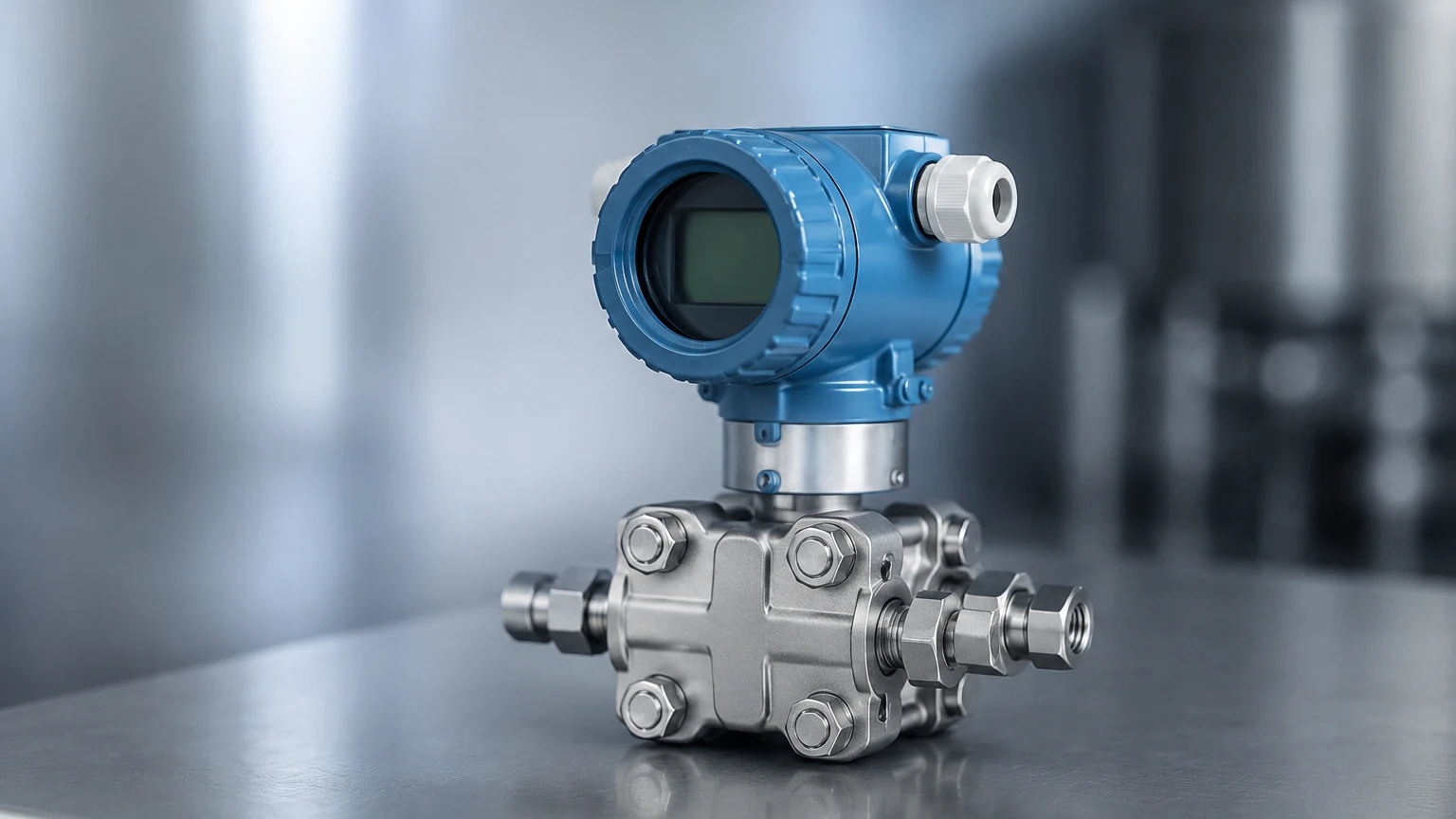
The internal architecture of a DP transducer typically consists of two pressure ports, often labeled as the "High Side" (H) and the "Low Side" (L). These ports are separated by a physical barrier, usually a sensing diaphragm. When fluid pressure is applied to both sides, the diaphragm deflects toward the side with lower pressure.
This physical displacement is converted into an electrical signal through various technologies:
* Piezoresistive Sensing: Strain gauges are bonded to the diaphragm. As the diaphragm deforms, the electrical resistance of the gauges changes proportionally to the pressure difference.
* Capacitance Sensing: The diaphragm acts as a movable plate between two fixed capacitor plates. Deflection changes the capacitance, which is then converted into a high-precision signal.
* Inductive Sensing: The movement of a core attached to the diaphragm alters the inductance of a nearby coil.
In modern industrial contexts, the term "transducer" is often used interchangeably with "transmitter." Technically, a transducer provides a raw voltage or millivolt output, while a transmitter includes signal conditioning circuitry to provide a standardized output, such as 4-20mA, HART, or Modbus, suitable for long-distance transmission to a PLC or DCS. For more information on integrated measurement solutions, you can visit the Main Page.
Applications in Industrial Level Measurement
One of the primary uses of a differential pressure transducer is determining the level of liquid in a vessel. This is based on the principle of hydrostatic head pressure. The pressure exerted by a liquid column is directly proportional to its height and the density of the fluid.
Open Tank Level Measurement
In an open (vented) tank, the low-side port of the DP transducer is left open to the atmosphere. The high-side port is connected to the bottom of the tank. The pressure measured is simply the hydrostatic weight of the liquid.
Formula: $P = ρ × g × h$
Where:
* $P$ = Pressure (Pascals or kPa)
* $ρ$ (rho) = Density of the liquid ($kg/m^3$)
* $g$ = Gravitational acceleration ($9.81 m/s^2$)
* $h$ = Height of the liquid (meters)
Pressurized (Closed) Tank Level Measurement
In pressurized vessels, such as those found in chemical processing or oil and gas, the overhead gas pressure (blanket pressure) adds to the total pressure at the bottom. To measure only the liquid level, the gas pressure must be subtracted.
By connecting the high-side port to the bottom of the tank and the low-side port to the top (the vapor space), the transducer cancels out the common gas pressure. The resulting differential pressure reflects only the liquid column height. This is a critical application for DP technology where ultrasonic or radar sensors might struggle with foam or heavy vapor layers.
Key Selection Criteria for Engineering Specifications
Selecting the correct DP transducer requires a thorough analysis of the process environment. Using an incorrectly specified instrument can lead to premature failure or inaccurate data.
| Criteria | Description | Considerations |
| :— | :— | :— |
| Pressure Range | The maximum and minimum expected differential. | Ensure the "Upper Range Limit" (URL) covers process upsets. |
| Static Pressure | The total pressure the housing must withstand. | A transducer might measure 10 kPa DP but must withstand 10 MPa static pressure. |
| Wetted Materials | Materials in contact with the process fluid. | 316L Stainless Steel, Hastelloy C, or Monel for corrosive media. |
| Accuracy | The allowable margin of error. | Typically expressed as a percentage of the calibrated span (e.g., ±0.075%). |
| Temperature Limits | Ambient and process temperature ranges. | Extreme heat may require remote seals or cooling capillaries. |
| Output Protocol | How the data is transmitted. | 4-20mA is standard; HART allowed for remote configuration and diagnostics. |
Installation Best Practices and Manifold Integration
The physical installation of a differential pressure transducer is as important as its electronic calibration. Improper piping (impulse lines) is the leading cause of measurement error in DP systems.
Impulse Line Configuration
Impulse lines are the small-diameter pipes that carry the process pressure to the transducer.
* Gas Measurement: The transducer should be mounted above the tapping point so that any condensate drains back into the process line.
* Liquid Measurement: The transducer should be mounted below the tapping point to ensure impulse lines remain full of liquid and air bubbles can escape upward.
Use of Manifolds
In industrial B2B applications, DP transducers are almost always installed with a valve manifold (3-way or 5-way). These manifolds allow for:
1. Isolation: Closing the process valves to remove the instrument without shutting down the line.
2. Equalization: Opening a bypass valve to ensure both sides of the diaphragm see the same pressure, allowing for zero-point calibration under static pressure.
3. Venting: Safely bleeding off trapped pressure or fluids before maintenance.
Limitations and Potential Operational Risks
While highly reliable, DP transducers have specific limitations that engineers must mitigate:
1. Density Sensitivity: Since the measurement relies on $ρ$ (density), any change in the fluid's temperature that affects its density will introduce a linear error in level measurement. Compensation via a temperature sensor is often required for high-precision applications.
2. Clogging and Sedimentation: If the process fluid contains solids, impulse lines can clog. In these scenarios, "Remote Seals" (diaphragm seals connected via oil-filled capillaries) are used to keep the process fluid out of the instrument body.
3. Hydrogen Permeation: In high-pressure hydrogen service, hydrogen atoms can diffuse through standard stainless steel diaphragms, causing internal damage. Gold-plated diaphragms are the standard solution for these specific industrial risks.
4. Dry Leg vs. Wet Leg Issues: In closed tank level measurement, if the vapor in the low-side impulse line condenses, it creates a "wet leg." If this condensation is inconsistent, the zero-point of the measurement will drift. Constant-level pots or remote seals are used to manage this.
Comparison with Alternative Level Measurement Technologies
To better understand when to deploy a DP transducer, it is helpful to compare it with other common industrial level sensors.
* Radar (Non-Contact): Excellent for corrosive or high-temperature liquids where no contact is desired. However, radar can be expensive and may be affected by internal tank obstructions or heavy foam. DP is often more cost-effective for clean liquids in pressurized tanks.
* Ultrasonic: Ideal for simple water treatment applications. It is limited by vacuum conditions and high-pressure environments where sound waves cannot propagate effectively. DP transducers excel in these high-pressure/vacuum scenarios.
* Hydrostatic (Submersible): These are essentially single-port pressure transducers. They are excellent for reservoirs and deep wells but cannot compensate for tank pressure in closed systems, making the DP transducer the superior choice for process vessels.
Frequently Asked Questions (FAQ)
Q: Can a differential pressure transducer measure flow?
A: Yes. By placing a primary flow element (like an orifice plate or Venturi tube) in a pipe, a pressure drop is created. The DP transducer measures this drop, and since flow is proportional to the square root of the differential pressure ($Q ∝ √ΔP$), the flow rate can be calculated.
Q: What is the difference between "Turndown Ratio" and "Rangeability"?
A: In the context of DP transducers, these terms refer to the ratio between the maximum and minimum measurable span while maintaining accuracy. A 100:1 turndown means a sensor with a 1000 kPa limit can be calibrated to measure a span as small as 10 kPa without significant loss of precision.
Q: How often should a DP transducer be calibrated?
A: This depends on the criticality of the process and the stability of the instrument. Most modern digital DP transmitters have high long-term stability (e.g., ±0.1% per 5-10 years), but regulatory requirements often dictate annual or biennial verification.
Q: What are remote seals?
A: Remote seals use a flexible diaphragm at the process connection, linked to the transducer via a capillary tube filled with silicone or other transmission oil. This prevents the process fluid from entering the instrument, which is vital for hygienic applications (food/pharma) or highly viscous fluids.
By understanding what is differential pressure transducer and its operational nuances, process engineers can ensure more reliable measurements and longer instrument lifespans. Whether for monitoring the level of a pressurized chemical reactor or measuring steam flow in a power plant, the DP transducer remains a cornerstone of industrial automation.