Subsea Flow Meters
Subsea Flow Meters
Subsea flow meters are specialized instruments designed to measure the flow rates of fluids—typically crude oil, natural gas, and produced water—directly on the seabed. These devices are integral components of Subsea Production Systems (SPS), providing critical data for reservoir management, flow assurance, and fiscal allocation. Unlike topside flow meters, subsea variants must withstand extreme external hydrostatic pressures, corrosive saltwater environments, and the internal stresses of high-pressure, high-temperature (HPHT) well streams.
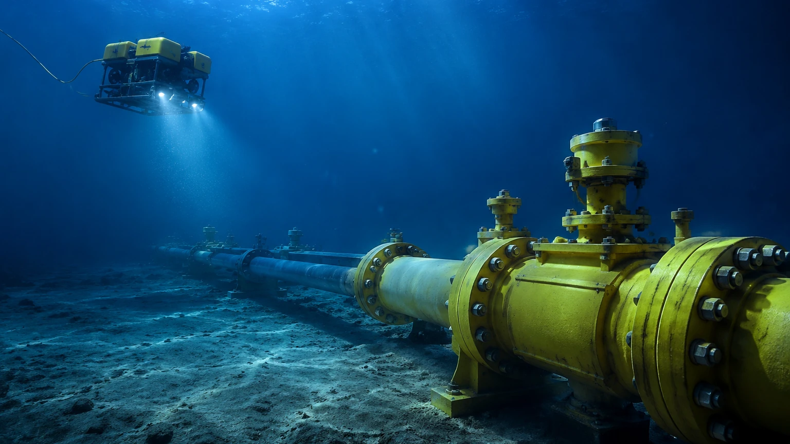
In the context of modern offshore engineering, the accuracy and reliability of subsea flow meters are paramount. Because these instruments are often located hundreds or thousands of meters below the surface, maintenance is prohibitively expensive, requiring Remotely Operated Vehicles (ROVs) or specialized vessels. Consequently, the selection process focuses heavily on long-term stability and robust mechanical design.
Measurement Principles of Subsea Flow Meters
Before selecting a meter, it is essential to understand the physics governing different measurement technologies. Subsea applications typically utilize one of the following four principles.
1. Differential Pressure (DP) – Venturi Meters
Differential pressure meters operate on Bernoulli’s principle, which states that an increase in the speed of a fluid occurs simultaneously with a decrease in static pressure. A Venturi meter features a constricted section (the throat) that increases flow velocity. By measuring the pressure difference between the upstream section and the throat, the mass or volumetric flow rate can be calculated.
* Subsea Application: Venturi meters are the industry standard for subsea use due to their lack of moving parts and high mechanical integrity. They are often used in single-phase or high-gas-volume-fraction (GVF) streams.
2. Ultrasonic Transit-Time
Ultrasonic flow meters utilize sound waves to determine fluid velocity. Pairs of transducers send and receive ultrasonic pulses diagonally across the pipe. The pulse traveling with the flow moves faster than the pulse traveling against it. The difference in transit time is directly proportional to the fluid velocity.
* Subsea Application: These meters provide high accuracy and a wide turndown ratio. However, the transducers must be housed in pressure-compensated or high-strength canisters to survive the deep-sea environment.
3. Coriolis Mass Flow
Coriolis meters measure mass flow directly by inducing a vibration in a set of tubes through which the fluid passes. The fluid’s inertia causes the tubes to twist slightly, and this phase shift is measured by sensors. The degree of twist is proportional to the mass flow rate, while the vibration frequency provides a density measurement.
* Subsea Application: While highly accurate, Coriolis meters are less common in subsea environments because the vibrating tubes are sensitive to external vibrations and the thick-walled housings required for deep-sea pressure can dampen the measurement signal.
4. Electromagnetic Flow Meters
These meters operate based on Faraday’s Law of Electromagnetic Induction. As a conductive fluid (such as produced water or seawater) passes through a magnetic field, it generates a voltage proportional to its velocity.
* Subsea Application: Primarily used for water injection lines or chemical injection monitoring where the fluid is sufficiently conductive.
Practical Selection Criteria
Choosing the correct subsea flow meter requires a multi-disciplinary approach. Engineers must balance the fluid properties with the environmental constraints of the deployment site.
Fluid Composition and Phase
The most significant factor is whether the flow is single-phase (liquid or gas) or multiphase (a mixture of oil, water, and gas). Single-phase meters are simpler and more cost-effective but are prone to significant errors if gas bubbles or water droplets are present. Multiphase Flow Meters (MPFM) often combine multiple principles—such as a Venturi for total flow and a gamma-ray densitometer for phase fraction—to provide accurate data for each component.
Design Pressure and Temperature
Subsea meters must be rated for both internal process pressure (often exceeding 690 bar or 10,000 psi) and external hydrostatic pressure. Temperature ratings must account for the high temperatures of the wellbore (up to 150°C) and the near-freezing temperatures of the deep-ocean floor (approx. 2°C to 4°C).
Turndown Ratio
The turndown ratio refers to the range of flow rates the meter can measure accurately. As a well matures, its production rate typically declines. A meter with a high turndown ratio ensures that the device remains useful throughout the entire life of the field (LoF) without requiring a change-out.
Material Compatibility
Materials must resist both internal erosion from sand and corrosion from H2S and CO2 (sour service). Common materials include Duplex or Super Duplex stainless steel and Inconel alloys. All external surfaces must be compatible with cathodic protection systems used on the subsea manifold.
Comparison Table: Subsea Flow Meter Technologies
| Technology | Accuracy (Typical) | Turndown Ratio | Recommended Fluid | Primary Limitation |
| :— | :— | :— | :— | :— |
| Venturi (DP) | ±1.0% to 3.0% | 10:1 | Single-phase / Wet Gas | High pressure loss at throat |
| Ultrasonic | ±0.5% to 1.0% | 50:1 | Clean liquids / Gas | Sensitive to solid particles |
| Coriolis | ±0.1% to 0.5% | 100:1 | Liquids / Slurries | Heavy and bulky for subsea |
| Electromagnetic | ±0.5% | 20:1 | Conductive liquids | Cannot measure oil or gas |
Installation and Integration Considerations
Successful deployment of subsea flow meters involves more than just the instrument itself. The integration into the subsea architecture is critical for long-term performance.
1. ROV Interfacing: The meter must be designed for installation and retrieval by an ROV. This includes specialized "buckets" for torque tools and handles that allow a robotic arm to position the device.
2. Signal Transmission: Data is typically transmitted via the Subsea Control Module (SCM). Common protocols include MODBUS or CANbus over a Subsea Instrumentation Interface Standard (SIIS). Ensuring electromagnetic compatibility (EMC) is vital to prevent interference with other subsea sensors.
3. Redundancy: Because retrieval is expensive, many subsea flow meters are installed in redundant pairs or include redundant sensors within a single housing to ensure continuous data availability.
4. Upstream/Downstream Piping: Like topside meters, subsea meters require specific lengths of straight piping to ensure a stable flow profile. In compact subsea manifolds, flow conditioners may be necessary to mitigate the effects of bends and valves.
While flow measurement is a distinct discipline, it is often paired with level measurement in subsea separation units. For engineers looking to understand the broader scope of industrial measurement technologies, including how level sensors integrate into automated systems, visiting the Main Page of specialized manufacturers like Welk provides a comprehensive overview of related instrumentation.
Limitations and Risks
Despite advancements in subsea engineering, several risks remain inherent to subsea flow measurement:
* Calibration Drift: Once a meter is installed on the seabed, physical calibration against a prover is impossible. Engineers must rely on "virtual metering" or diagnostic software to detect drift.
* Wax and Scale Build-up: Crude oil often contains paraffin waxes or mineral scales that can precipitate out and coat the internal surfaces of the meter. This changes the internal diameter and leads to significant measurement bias.
* Signal Attenuation: In ultrasonic meters, the presence of sand or gas bubbles can scatter the signal, leading to a loss of data.
* Power Supply: Subsea instruments operate on limited power budgets provided by the umbilical cable from the surface. High-power instruments may require dedicated power management.
Frequently Asked Questions (FAQs)
What is the difference between a subsea flow meter and a multiphase flow meter?
A subsea flow meter is any flow measurement device rated for subsea use. A multiphase flow meter (MPFM) is a specific type of meter designed to measure the individual flow rates of oil, water, and gas simultaneously without separating them first. Many subsea meters are MPFMs because separating fluids on the seabed is complex and expensive.
How long do subsea flow meters typically last?
Most subsea instruments are designed for a service life of 20 to 25 years, matching the expected life of the subsea field. This requires high-grade materials and electronics with high Mean Time Between Failures (MTBF) ratings.
Can subsea flow meters be repaired?
Generally, no. Subsea flow meters are considered "replace-on-failure" items. If a meter fails, an ROV must disconnect the module and bring it to the surface for repair or replacement. This is why reliability is prioritized over the initial purchase cost.
How is the data from the seabed sent to the platform?
Data is sent through electrical or fiber-optic cables within the subsea umbilical. The flow meter connects to a Subsea Control Module (SCM), which aggregates data from various sensors and transmits it to the Master Control Station (MCS) on the surface facility or onshore.
Summary of Confirmation Steps for Project Engineers
Before finalizing a subsea flow meter specification, project teams should confirm the following:
* Fluid Properties: Obtain a detailed fluid analysis, including expected GVF (Gas Volume Fraction) and WLR (Water Liquid Ratio) over the life of the well.
* Structural Loads: Ensure the meter housing can withstand the mechanical loads of the subsea jumper or manifold.
* Communication Protocol: Verify that the meter's electronics are compatible with the existing Subsea Control System (SCS) architecture.
* Intervention Strategy: Confirm that the meter is accessible by the specific ROV models available in the region of operation.
By carefully evaluating these factors and understanding the underlying measurement principles, engineers can ensure accurate production data and robust flow assurance for the duration of the subsea project.