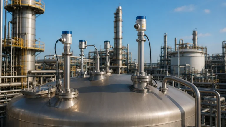
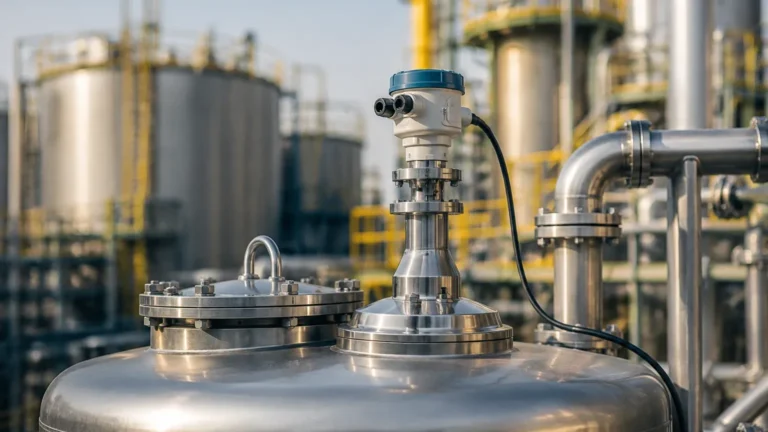
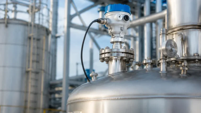
4 20ma Radar Level Transmitter
4 20ma Radar Level Transmitter: Engineering Principles and Application Selection
In the landscape of industrial process automation, the 4 20ma radar level transmitter has established itself as the gold standard for non-contact level measurement. By combining the precision of microwave technology with the robustness of the industry-standard current loop, these instruments provide reliable data in environments where traditional sensors—such as ultrasonic or hydrostatic transmitters—often fail.
For engineers and procurement specialists, understanding the nuances of Radar Level Meters is essential for ensuring plant safety, reducing maintenance overhead, and optimizing process efficiency. This guide details the measurement principles, selection criteria, and installation constraints necessary for deploying radar technology effectively.
Measurement Principles of Radar Level Technology
Radar level transmitters operate on the principle of Time Domain Reflectometry (TDR) or Frequency Modulated Continuous Wave (FMCW). Both methods rely on the emission of electromagnetic waves, which travel at the speed of light, reflect off the surface of the medium, and return to the sensor antenna.
Pulse Radar (Time of Flight)
Pulse radar transmitters emit short microwave pulses toward the material surface. The instrument measures the time elapsed between the emission of the pulse and the reception of the reflected signal. Since the speed of electromagnetic waves is constant (approximately 300,000 km/s), the distance (D) is calculated as:
D = (c × t) / 2
Where *c* is the speed of light and *t* is the transit time. The level of the medium is then derived by subtracting the distance from the known total height of the vessel.
FMCW (Frequency Modulated Continuous Wave)
Modern high-precision radar transmitters often utilize FMCW technology. Instead of discrete pulses, the transmitter emits a continuous signal with a constantly changing frequency (a frequency sweep). The reflection returns with a frequency shift compared to the signal being emitted at that exact moment. The difference in frequency is directly proportional to the distance. FMCW is generally preferred for applications requiring high accuracy (up to ±1 mm) and for measuring materials with low dielectric constants.
The Role of the 4-20mA Interface
The "4 20ma radar level transmitter" designation refers to the output signal used to communicate with control systems like PLCs (Programmable Logic Controllers) or DCS (Distributed Control Systems).
Advantages of the 4-20mA Current Loop
1. Noise Immunity: Unlike voltage signals, current signals are highly resistant to electromagnetic interference (EMI), which is common in industrial environments with large motors and high-voltage cabling.
2. Long-Distance Transmission: A 4-20mA signal can travel hundreds of meters without significant signal degradation.
3. Fault Diagnostics (Live Zero): Because the signal never drops to 0mA during normal operation (4mA represents the 0% level), a reading of 0mA immediately indicates a loop break or sensor failure.
4. HART Protocol Compatibility: Most 4-20mA radar transmitters support HART (Highway Addressable Remote Transducer) communication, allowing digital configuration and diagnostic data to be superimposed on the analog signal.
Technical Selection Criteria
Selecting the correct radar transmitter requires an evaluation of frequency, antenna design, and the physical properties of the medium.
Frequency Considerations: 26GHz vs. 80GHz
The frequency of the radar signal determines the beam angle and the ability to penetrate dust or steam.
* 26GHz Radar: Features a wider beam angle. It is robust and suitable for many liquid applications but may struggle in narrow tanks with internal obstructions where the beam might hit agitators or ladders.
* 80GHz Radar: Offers a very narrow beam angle (often as small as 3°). This makes it ideal for tall, narrow silos or tanks with complex internal structures. The high frequency also provides better reflection from turbulent surfaces and low-dielectric materials.
Selection Table: Radar Technology Comparison
| Feature | 26GHz Pulse/FMCW | 80GHz FMCW | Guided Wave Radar (GWR) |
| :— | :— | :— | :— |
| Measurement Range | Up to 30m | Up to 120m | Up to 75m |
| Accuracy | ±3mm to ±5mm | ±1mm | ±2mm |
| Beam Angle | 8° – 20° | 3° – 8° | N/A (Contact) |
| Best For | General liquids, large tanks | Narrow tanks, solids, high precision | Low dielectric liquids, interface |
| Process Temp. | -40°C to +250°C | -40°C to +200°C | -200°C to +450°C |
| Max Pressure | 40 bar | 20 bar | 400 bar |
Installation Considerations and Constraints
Correct installation is the most critical factor in the performance of a 4 20ma radar level transmitter. Even the most advanced sensor will provide erratic readings if the signal path is compromised.
1. Beam Path and Obstructions
The radar beam expands as it travels. The "keep-out zone" must be free of internal pipes, agitators, or structural reinforcements. If an obstruction is unavoidable, many modern transmitters offer "False Echo Suppression" software, allowing the user to map out static reflections so the sensor ignores them.
2. Nozzle Geometry
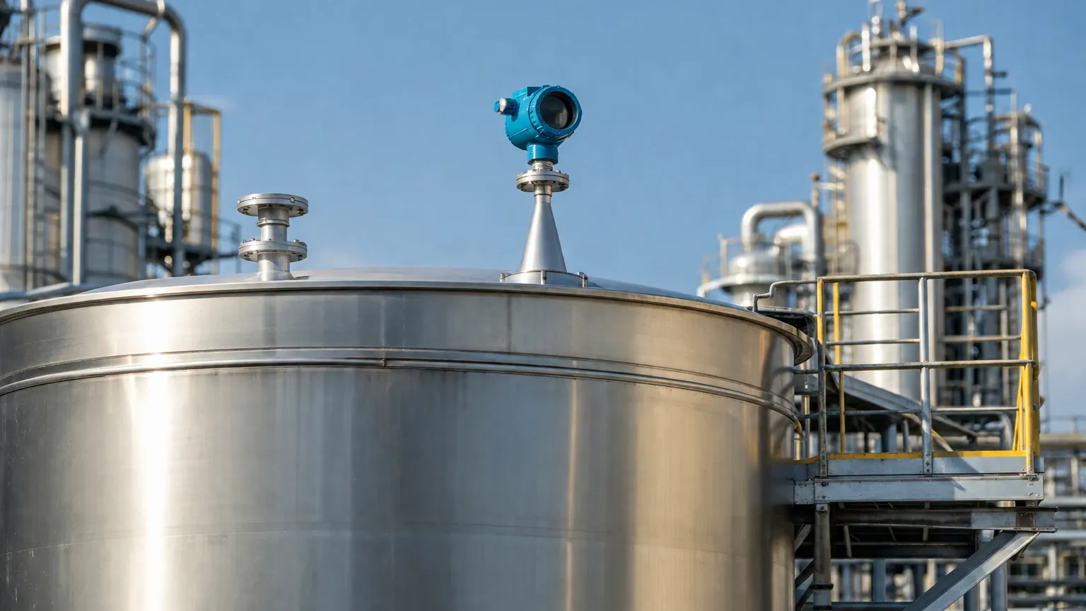
The antenna should ideally extend slightly beyond the mounting nozzle to prevent signal ringing within the nozzle itself. If the nozzle is very long or narrow, a specialized antenna extension or a high-frequency (80GHz) unit should be used to minimize interference.
3. The Dead Zone (Blocking Distance)
Every radar sensor has a minimum measurable distance near the antenna, known as the dead zone or blocking distance (typically 0.1m to 0.5m). The tank should never be filled into this zone, as the transmitter will lose the signal or report an error.
4. Orientation
For liquid applications, the transmitter should be mounted vertically (perpendicular to the surface). For bulk solids, an adjustable flange (aiming device) may be required to point the beam at the angle of repose of the material to ensure a strong return signal.
Limitations and Application Risks
While highly versatile, radar technology has specific limitations that engineers must account for during the design phase.
Dielectric Constant (εr)
The reflectivity of a material depends on its dielectric constant. Water has a high dielectric constant (εr ≈ 80) and reflects radar waves very well. In contrast, hydrocarbons, oils, and certain plastic pellets have low dielectric constants (εr < 2.0). If the εr is too low, the signal may pass through the material or be too weak to detect. In such cases, Guided Wave Radar or high-sensitivity 80GHz FMCW units are required.
Foam and Turbulence
Heavy, dense foam can absorb radar signals, leading to signal loss. While light foam is usually transparent to radar, thick chemical foams may require a stilling well or a different measurement technology altogether. Similarly, extreme surface turbulence can scatter the signal; using software averaging or a stilling well can mitigate this effect.
Dust and Condensation
In solids measurement, heavy dust can attenuate high-frequency signals. For these applications, antennas with integrated air-purge systems are used to keep the lens clean. In liquid tanks with high humidity, condensation on the antenna can cause signal drift. Choosing a PTFE-coated "drop" antenna helps moisture bead off and prevents buildup.
Frequently Asked Questions (FAQ)
Q: Can a 4 20ma radar level transmitter measure through a plastic tank lid?
A: Yes. Since plastic is non-conductive and has a low dielectric constant, radar waves can pass through it. This allows for non-invasive measurement from outside a plastic IBC or storage tank.
Q: What is the difference between 2-wire and 4-wire transmitters?
A: A 2-wire transmitter uses the same two wires for both power supply and the 4-20mA signal output, which simplifies wiring. A 4-wire transmitter uses two wires for power (often 220V AC or 24V DC) and two separate wires for the signal; these are typically used for high-power FMCW units or when heated antennas are required.
Q: How do I calibrate a 4-20mA radar sensor?
A: Most units are calibrated by setting the 4mA point (typically the empty tank distance) and the 20mA point (the full tank distance) via a local display, a handheld HART communicator, or laptop software. Because it is a non-contact measurement based on distance, it does not require a "wet calibration" with actual fluid if the tank dimensions are known accurately.
Q: Is radar suitable for vacuum or high-pressure tanks?
A: Yes. Unlike ultrasonic sensors, which require air to transmit sound, radar waves travel through a vacuum. Radar is highly effective in pressurized vessels, provided the process seal and antenna material are rated for the specific pressure and temperature.
Conclusion
The 4 20ma radar level transmitter is a cornerstone of modern industrial instrumentation. By selecting the appropriate frequency and antenna design, and adhering to strict installation guidelines regarding beam clearance and dielectric properties, facilities can achieve maintenance-free, high-precision level monitoring. For complex applications involving low-dielectric fluids or extreme dust, consulting with a technical specialist to perform a signal-to-noise calculation is recommended to ensure long-term operational reliability.