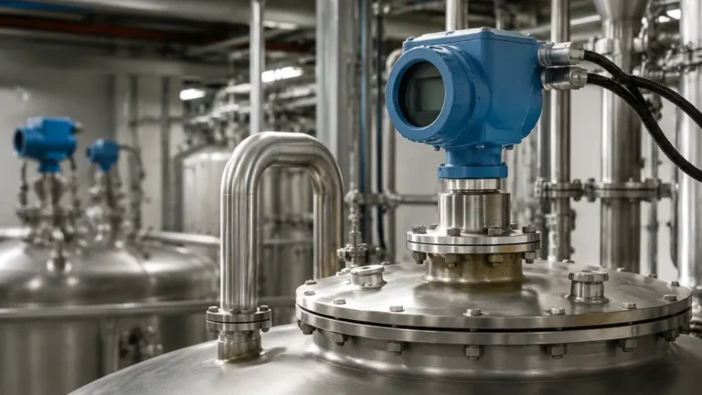
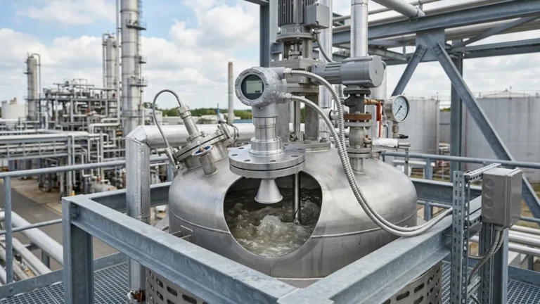
Radar Level Switch
Radar Level Switch
In modern industrial process control, point level detection serves as a critical safety and operational layer. While continuous level measurement provides a real-time gradient of vessel contents, the radar level switch is increasingly utilized as a high-reliability solution for overfill protection, dry-run prevention, and high/low-level alarming. Unlike traditional mechanical float switches or ultrasonic sensors, radar-based technology offers a non-contact, maintenance-free alternative that remains unaffected by changes in pressure, temperature, or vapor space composition.
This guide examines the engineering principles, selection criteria, and installation requirements for radar level switching technology, providing a framework for engineers and procurement professionals to specify the correct instrumentation for complex industrial environments.
1. Understanding the Measurement Principle
A radar level switch operates on the principle of microwave reflection. The device emits high-frequency electromagnetic pulses (typically in the 24 GHz to 80 GHz range) toward the material surface. When these waves encounter a change in the dielectric constant (εr) between the air/gas and the process media, a portion of the energy is reflected back to the sensor.
Time of Flight (ToF) and Signal Processing
The sensor measures the time interval between the emission of the pulse and the reception of the echo. This is known as the Time of Flight (ToF). In a switching application, the internal electronics compare the calculated distance against a pre-configured setpoint. When the media reaches the specified distance, the switch changes state (e.g., from normally open to normally closed).
Modern Radar Level Meters often utilize Frequency Modulated Continuous Wave (FMCW) technology. Instead of short pulses, FMCW systems emit a continuous signal with a constantly changing frequency. The difference in frequency between the emitted and received signal is directly proportional to the distance. For switching purposes, FMCW provides superior signal-to-noise ratios, allowing for reliable detection even in turbulent or agitated liquids.
2. Key Technical Specifications for Selection
Selecting a radar level switch requires an analysis of both the process media and the vessel environment. The following parameters are fundamental to ensuring instrument performance.
Dielectric Constant (εr)
The dielectric constant of the material determines the strength of the reflected signal. Materials with high dielectric constants, such as water (εr ≈ 80), reflect signals strongly. Hydrocarbons and organic solvents often have low dielectric constants (εr < 2.0), which may require high-sensitivity radar heads or guided wave radar configurations to ensure the switch triggers reliably.
Operating Frequency
* 24 GHz Radar: Suitable for most standard liquid applications. It has a wider beam angle, which can be advantageous in some large tanks but may encounter interference from internal obstructions.
* 80 GHz Radar: Features a much narrower beam angle and higher resolution. This is the preferred choice for small vessels, tanks with internal agitators, or applications requiring precise switching points near the bottom of a tank.
Process Conditions
Engineers must confirm the maximum operating temperature and pressure. Standard radar switches typically handle up to 150°C (302°F) and 40 bar (580 psi), though specialized high-temperature versions from manufacturers like Welk can extend this range significantly using cooling fins or ceramic seals.
3. Comparison with Alternative Point Level Technologies
To justify the investment in a radar level switch, it is helpful to compare it against other common industrial technologies.
| Technology | Media Compatibility | Maintenance Level | Impact of Vapor/Dust | Cost Profile |
| :— | :— | :— | :— | :— |
| Radar Level Switch | Liquids, Slurries, Solids | Very Low (Non-contact) | Negligible | Higher Initial |
| Ultrasonic Switch | Clean Liquids | Moderate (Sensor fouling) | High (Affected by temp/vapor) | Low to Medium |
| Tuning Fork | Liquids/Solids | Moderate (Contact-based) | None | Medium |
| Capacitance | Consistent Dielectrics | High (Build-up sensitive) | None | Medium |
| Float Switch | Clean Liquids | High (Mechanical wear) | None | Lowest |
4. Installation and Engineering Best Practices
The reliability of a radar level switch is heavily dependent on its physical installation. Incorrect placement can lead to false echoes or "dead zones" where the sensor fails to detect the media.
Nozzle Geometry and Placement
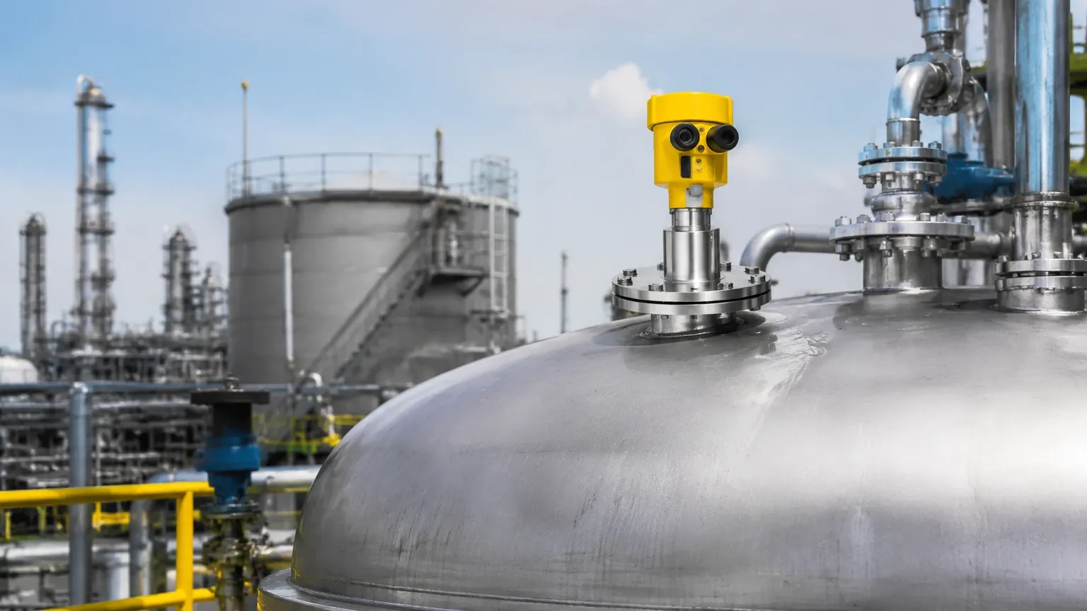
The sensor should be mounted away from the tank wall to prevent signal interference. A general rule is to maintain a distance of at least 200 mm (approx. 8 inches) from the wall. If the switch is installed on a nozzle, the nozzle height should be kept as short as possible to prevent the "ringing" effect, where the signal bounces within the nozzle before reaching the tank volume.
Avoiding Obstructions
Internal structures such as heating coils, ladders, and agitators act as reflectors. When using 24 GHz radar, the wider beam may hit these objects. In such cases, the use of a narrow-beam 80 GHz sensor or the implementation of "false echo suppression" (mapping out static reflections in the software) is required.
Dead Zones (Blocking Distance)
Every radar sensor has a minimum detection distance, often called the blocking distance or dead zone, typically ranging from 50 mm to 300 mm (2 to 12 inches) depending on the antenna design. The switch cannot detect media that enters this zone. For overfill protection, the sensor must be mounted high enough that the maximum possible liquid level remains below the dead zone.
5. Application-Specific Considerations
Chemical and Corrosive Media
In the chemical industry, the radar level switch must be isolated from aggressive vapors. PTFE or PFA coatings on the antenna are standard requirements. Because the measurement is non-contact, the sensor life is significantly longer than contact-based probes in corrosive service.
Solids and Powders
For bulk solids, the angle of repose must be considered. The radar signal may scatter if it hits a sloped surface of grain or plastic pellets. High-frequency radar with a narrow beam is generally more effective at capturing a return signal from uneven solid surfaces.
Foam and Turbulence
Heavy, dense foam can absorb radar signals, leading to signal loss. If the application involves thick foam (e.g., in fermentation or certain wastewater treatments), a guided wave radar switch or a lower frequency radar may be necessary to penetrate the foam layer and reach the liquid surface.
6. Limitations and Risk Mitigation
While highly versatile, radar level switches are not universal solutions. Engineers should be aware of the following limitations:
1. Extremely Low Dielectric Materials: For materials with εr < 1.4 (such as certain liquified gases), the reflected signal may be too weak for standard non-contact radar. Guided wave radar (GWR) is the recommended alternative here.
2. Vacuum Applications: While radar works in a vacuum, the sealing of the instrument must be rated for vacuum service to prevent air ingress or damage to the electronics.
3. Heavy Build-up: Although non-contact, if the antenna itself becomes coated in thick, conductive mud or crystallized product, the signal will be attenuated. Periodic inspection or the use of an air purge system may be required in extremely dusty or splashing environments.
7. Buyer’s Checklist: Information to Confirm
When sourcing a radar level switch from an international manufacturer, providing a complete data sheet ensures the instrument will perform as expected. Buyers should confirm the following:
* Media Type: Is it liquid, slurry, or solid? What is the dielectric constant?
* Vessel Dimensions: Total height, diameter, and nozzle specifications.
* Output Requirements: Do you require a relay (SPDT), PNP/NPN transistor output, or a 4-20mA signal with HART for switch-point programming?
* Certifications: Are Explosion-Proof (Ex-d) or Intrinsically Safe (Ex-ia) ratings required for hazardous areas?
* Process Interface: Threaded (G or NPT), Flanged (ANSI or DIN), or Hygienic (Tri-clamp) connections.
8. Frequently Asked Questions (FAQ)
Q: Can a radar level switch replace a continuous radar level meter?
A: A radar level switch is designed to provide a binary output at a specific point. While many continuous Radar Level Meters can be programmed with switch outputs, a dedicated switch is often a more cost-effective choice if only point detection (like a high-level alarm) is needed.
Q: How does steam affect the radar signal?
A: Unlike ultrasonic sensors, which are affected by changes in air density and temperature, radar signals are electromagnetic and travel through steam with minimal attenuation, making them ideal for boiler and steam-jacketed vessel applications.
Q: Is calibration required for a radar level switch?
A: Most modern radar switches are pre-calibrated at the factory. However, "zero-point" adjustment and switch-point configuration are typically performed during commissioning via an integrated display, a handheld programmer, or Bluetooth-connected software.
Q: What is the typical lifespan of a radar level switch?
A: Because there are no moving parts and the sensor does not typically contact the media, a high-quality radar switch from a professional manufacturer like Welk can have an operational lifespan exceeding 10 to 15 years in standard industrial environments.
Conclusion
The radar level switch represents the pinnacle of point level detection technology for the B2B industrial sector. By offering a non-contact, high-precision method for monitoring tank levels, it reduces maintenance overhead and improves process safety. When selecting a unit, engineers must prioritize the dielectric properties of the media and the physical constraints of the vessel to ensure long-term reliability. For applications involving complex geometries or low-dielectric fluids, consulting with a specialized manufacturer is recommended to determine the optimal frequency and antenna configuration.